


Quick Research
Generate reliable direction feasibility study reports for your R&D in just a few steps.

Technical Q&A
Discover and master advanced knowledge NOW. Basics, ideas, possibilities, all at once.

Find Solutions
As an expert in R&D theories, this can generate solutions to your technical problems instantly.

Evaluate Feasibility
Analyze your overall solution with one click, know your potential R&D risks in advance.

Monitor Landscape
Get weekly tech updates, stay abreast of the latest tech innovations and key insights.
Rubber rod and steel strand threading and pulling system before box girder pouring
A technology of rubber rods and steel strands, used in ceramic forming mandrels, ceramic forming machines, manufacturing tools, etc., can solve the problems of time-consuming and laborious operation, high risk factor, and achieve the advantages of reducing wear, smooth movement and reducing work intensity. Effect
- Summary
- Abstract
- Description
- Claims
- Application Information
AI Technical Summary
Problems solved by technology
Method used
Image

Examples
Embodiment 1
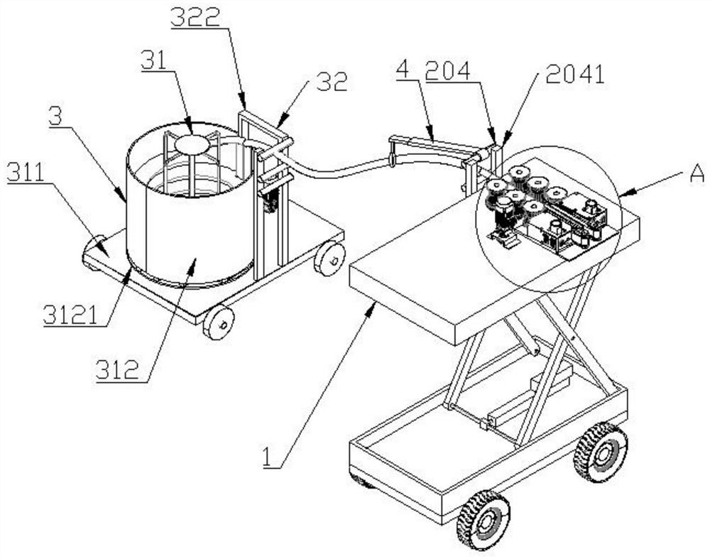
[0036] see Figure 1-3 , a rubber rod and steel strand threading and drawing system before box girder pouring, including a movable lifting bracket 1 and a threading and clamping mechanism 2 for rubber rods installed on the top surface of the bracket 1, which can be moved up and down The bracket 1 is preferably replaced by a mobile trolley equipped with automatic lifting. After the bracket 1 reaches the plugging rod station, the rubber rod is manually assisted, and then the anchor hole is accurately positioned, and the rubber rod is automatically inserted or pulled out. First pull out the steel wire in the middle, then pull out the rubber rod, coil it while pulling it out, or manually assist in feeding the steel strand bundle, then accurately locate the anchor hole, automatically thread the bundle, and set the traction mechanism at the other end, and pull it while pulling it bundle.
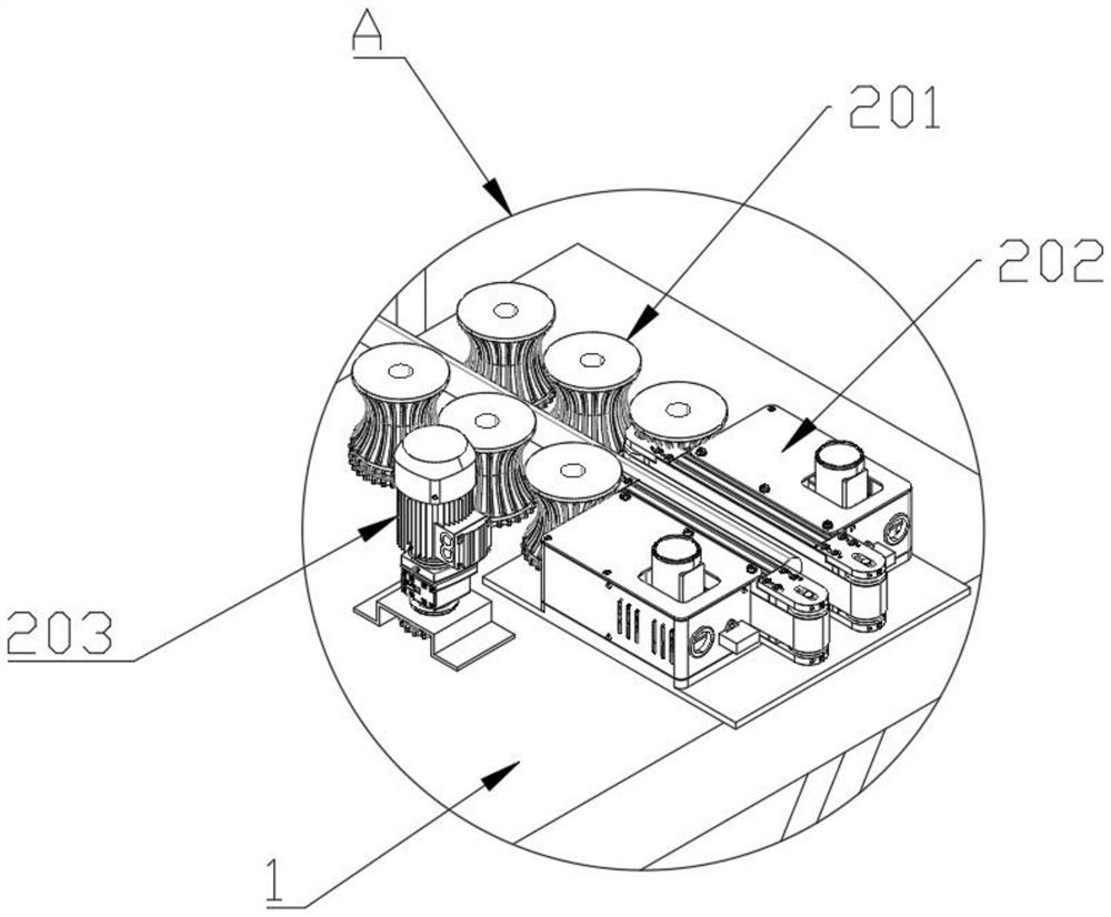
[0037] The threading clamping mechanism 2 includes several groups of clamping wheels 201 inst...
Embodiment 2
[0039] see Figure 1-5 , a rubber rod and steel strand threading and drawing system before box girder pouring, also includes a storage mechanism 3 for rubber rods used in conjunction with the threading clamping mechanism 2, the storage mechanism 3 includes a collection device 31 and Limiting device 32.
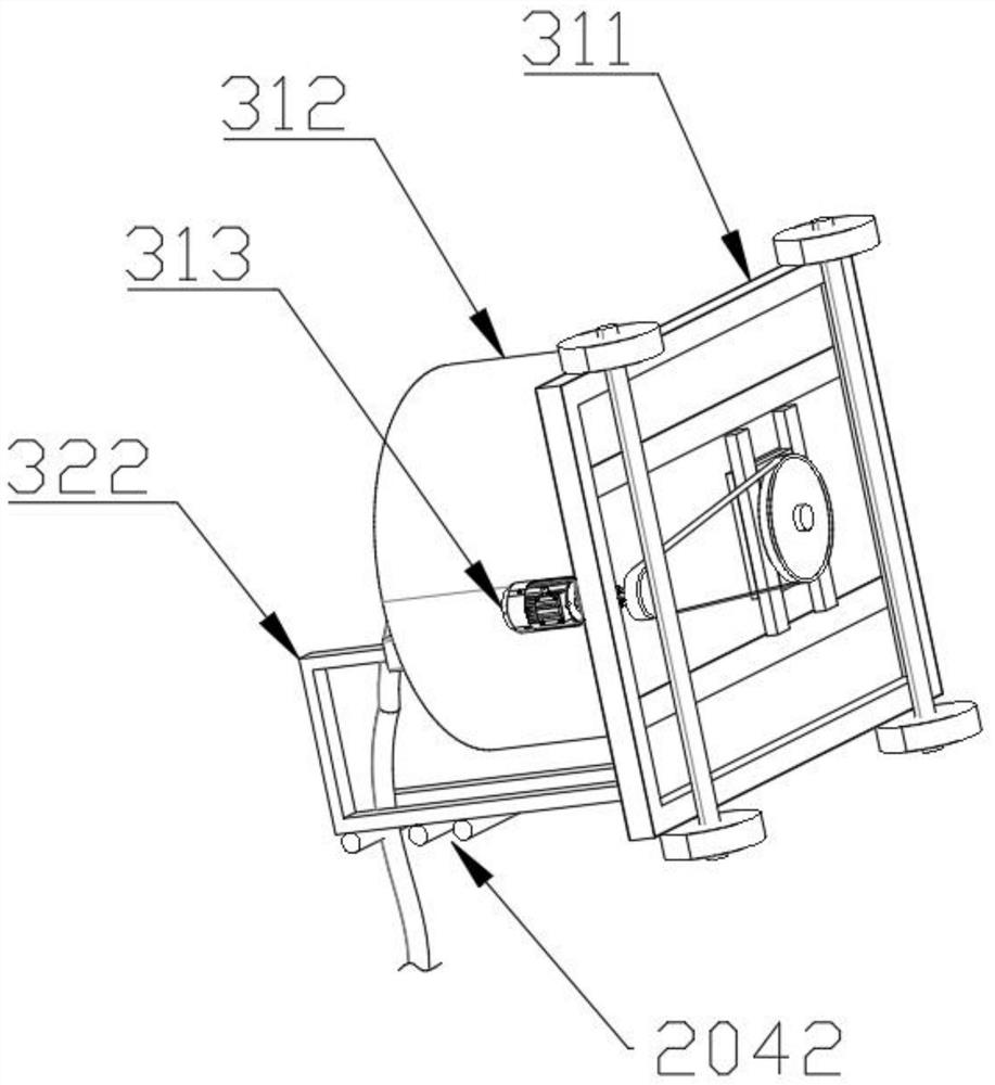
[0040]The collection device 31 includes a movable base 311, a collection bucket 312 installed on the top surface of the base 311 for storing rubber sticks, and a No. 2 motor 313 installed on the top surface of the base 311 to provide rotational power for the collection bucket 312, and a limit device 32 includes a limit frame 321 arranged inside the collection bucket 312, a support rod 322 is welded on one side of the base 311, and a limit rod 323 is welded on the other end of the support rod 322. The base 311 is preferably replaced by a mobile trolley, and the limit frame 321 is coaxial with the collection bucket 312, and is used to limit the steel strands in the collection b...
Embodiment 3
[0043] see figure 1 , Figure 6 and Figure 7 , a rubber rod and steel strand threading and drawing system before box girder pouring, the guide frame 204 is sleeved with a wire harness guide mechanism 4, and the wire harness guide mechanism 4 includes a cylinder that is sleeved and clamped on the guide frame 204 Sleeve 401, the outer wall of the cylindrical sleeve 401 is welded with a hollow plate 402, the interior of the hollow plate 402 is plugged with a telescopic plate 403, the telescopic plate 403 can telescopically slide inside the hollow plate 402, and the bottom of the telescopic plate 403 is welded with a connection Rod 404, the bottom of connecting rod 404 is welded with guide ring 405, and the inner wall of guide ring 405 is provided with several movable grooves 406, and the inner two sides of movable groove 406 are equipped with rotating shaft 407, and between rotating shaft 407 is fixed with rotatable The roller 408 of the wire harness guide mechanism 4 can supp...
PUM
 Abstract
Description
Claims
Application Information
 - R&D Engineer
- R&D Manager
- IP Professional
- Industry Leading Data Capabilities
- Powerful AI technology
- Patent DNA Extraction
Browse by: Latest US Patents, China's latest patents, Technical Efficacy Thesaurus, Application Domain, Technology Topic, Popular Technical Reports.
© 2024 PatSnap. All rights reserved.Legal|Privacy policy|Modern Slavery Act Transparency Statement|Sitemap|About US| Contact US: help@patsnap.com