
Tread pattern grooving device for tire retreading

A tread pattern and tire retreading technology, which is applied in the field of tire processing, can solve the problems of different depths of water guide grooves, racing hazards, shaking water guide grooves, etc., to ensure water conduction performance and grip, save labor costs, and save operation time Labor-saving effect

Pending Publication Date: 2022-02-15
山东银宝轮胎集团有限公司
View PDF5 Cites 0 Cited by
  • Summary
  • Abstract
  • Description
  • Claims
  • Application Information

AI Technical Summary

Problems solved by technology

The grooving mainly includes the water guide groove and the transverse groove of the tire. In the actual grooving process, the grooving tool is manually operated. It is more handy to operate the short groove such as the transverse groove. However, for the water guide groove For this annular groove, there are many inconveniences in the actual operation process: first, the distance between each water guide groove is not easy to control, and deviations often occur in the actual operation process; second, the distance between each water guide groove Insufficient smoothness, if the operator is inexperienced, it is easy to appear "jittery" water guide grooves; thirdly, the depth of each water guide groove is different, which directly affects the overall water guide performance and grip performance of the tire, and is also a potential danger to the racing car

Method used


Image

  • Tread pattern grooving device for tire retreading
  • Tread pattern grooving device for tire retreading
  • Tread pattern grooving device for tire retreading

Examples


Embodiment Construction

[0032] In order to clearly illustrate the technical features of this solution, the present invention will be described in detail below through specific implementation methods and in conjunction with the accompanying drawings. In the following description, many specific details are set forth in order to fully understand the application, but the application can also be implemented in other ways different from those described here, therefore, the protection scope of the application is not limited by the specific details disclosed below. EXAMPLE LIMITATIONS.

[0033] In addition, in the description of the present application, it should be understood that the terms "center", "upper", "lower", "front", "rear", "left", "right", "vertical", "horizontal" ", "Top", "Bottom", "Inner", "Outer", "Axial", "Radial", "Circumferential" and other indicated orientations or positional relationships are based on the orientations or positional relationships shown in the drawings , is only for the ...


PUM


Abstract

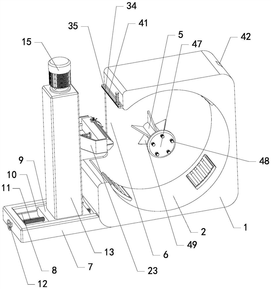
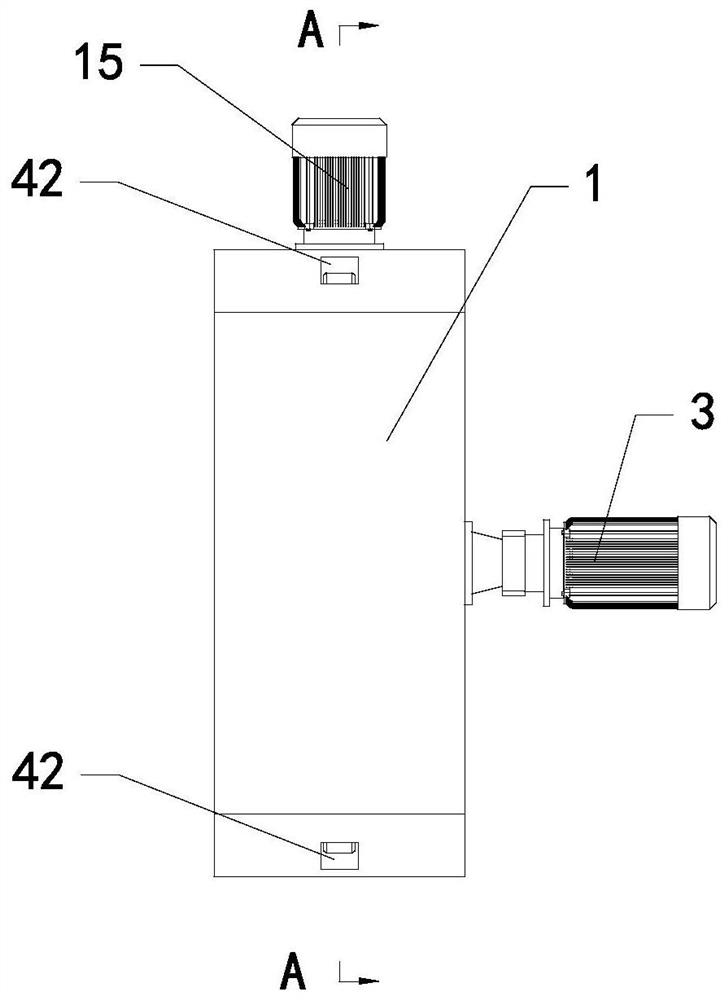
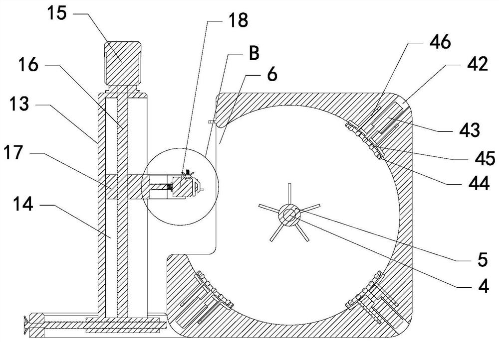
The invention relates to the technical field of tire machining, in particular to a tread pattern grooving device for tire retreading. The device includes a fixing base, the center of the front side wall of the fixing base is inwards provided with a wheel containing groove, a driving motor is arranged on the rear side of the fixing base, an output shaft of the driving motor vertically and movably penetrates through the center of the rear side wall of the fixing base to be connected with a rotating shaft arranged in the wheel containing groove, and a fixing piece is arranged at the front end of the rotating shaft. The rotating shaft in the wheel containing groove is movably sleeved with a sleeve abutting against the inner wall of the fixing base, a machining channel communicated with the wheel containing groove is formed in the left end of the fixing base, a supporting frame is arranged on the left side wall of the fixing base below the machining channel, and a machining mechanism is clamped in the supporting frame through a first-order adjusting mechanism arranged at the bottom of the machining mechanism. And a line drawing mechanism is arranged on the side wall of the fixing seat above the machining channel. The device is reasonable in structural design and convenient to operate, adopts semi-automatic mechanical work, effectively liberates manpower, and solves many problems existing in the machining process of a water chute in the prior art.

Description

technical field [0001] The invention relates to the technical field of tire processing, in particular to a tread pattern groove device for retreading tires. Background technique [0002] Tires are circular elastic rubber products that roll on the ground and are assembled on various vehicles or machinery. They can be classified into car tires, racing tires, engineering vehicle tires, aircraft tires, etc. according to their types. Especially the racing tires used in F1 Formula One events are generally made of soft, high-quality synthetic rubber. This rubber is like an eraser, which generates heat during friction, and when turning, the continuous lateral force will also cause the tire to heat up. Therefore, the replacement frequency of this kind of racing tires is very high. Usually, during the race, the tires need to be replaced every 50 kilometers. Flat tire phenomenon. [0003] However, the cost of such racing tires is high. In order to reduce the cost of tires, save ener...

Claims


Application Information

Patent Timeline
IPC IPC(8): B26D7/00B26D3/06B25H7/04
CPCB26D3/06B26D7/0006B26D7/00B25H7/04
Inventor 刘奇
Owner 山东银宝轮胎集团有限公司
Learn More