


Quick Research
Generate reliable direction feasibility study reports for your R&D in just a few steps.

Technical Q&A
Discover and master advanced knowledge NOW. Basics, ideas, possibilities, all at once.

Find Solutions
As an expert in R&D theories, this can generate solutions to your technical problems instantly.

Evaluate Feasibility
Analyze your overall solution with one click, know your potential R&D risks in advance.

Monitor Landscape
Get weekly tech updates, stay abreast of the latest tech innovations and key insights.
Optical transmission network wave channel configuration method and device, electronic equipment and storage medium
A technology of optical transmission network and configuration method, which is applied in the field of optical communication, can solve the problems of waste, multiple overlapping of channel usage, and high cost of expansion, and achieve the effect of reducing the cost of expansion
- Summary
- Abstract
- Description
- Claims
- Application Information
AI Technical Summary
Problems solved by technology
Method used
Image

Examples
Embodiment 1
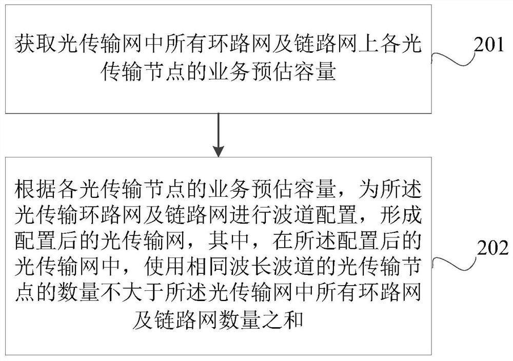
[0045] figure 2 is a schematic flowchart of a method for configuring optical transmission network channels provided by the present application, as shown in figure 2 As shown, the method includes:
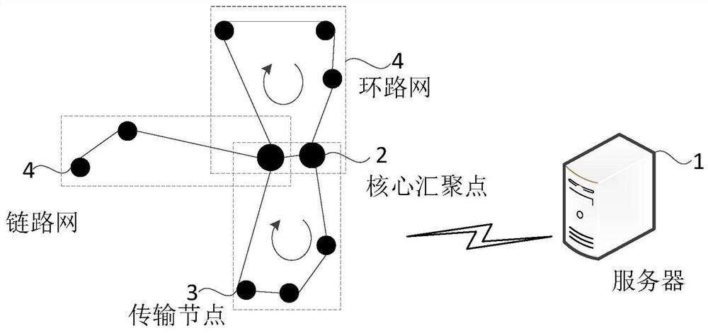
[0046] Step 201. Obtain the estimated service capacity of each optical transmission node on all ring networks and link networks in the optical transmission network. The optical transmission network refers to the same type of optical transmission network in which the optical core aggregation nodes are located in the same administrative area;
[0047] Step 202: According to the estimated service capacity of each optical transmission node, perform channel configuration for the optical transmission ring network and the link network to form a configured optical transmission network, wherein, in the configured optical transmission network , the number of optical transmission nodes using the same wavelength channel is not greater than the sum of the numbers of all optical transmission r...
Embodiment 2
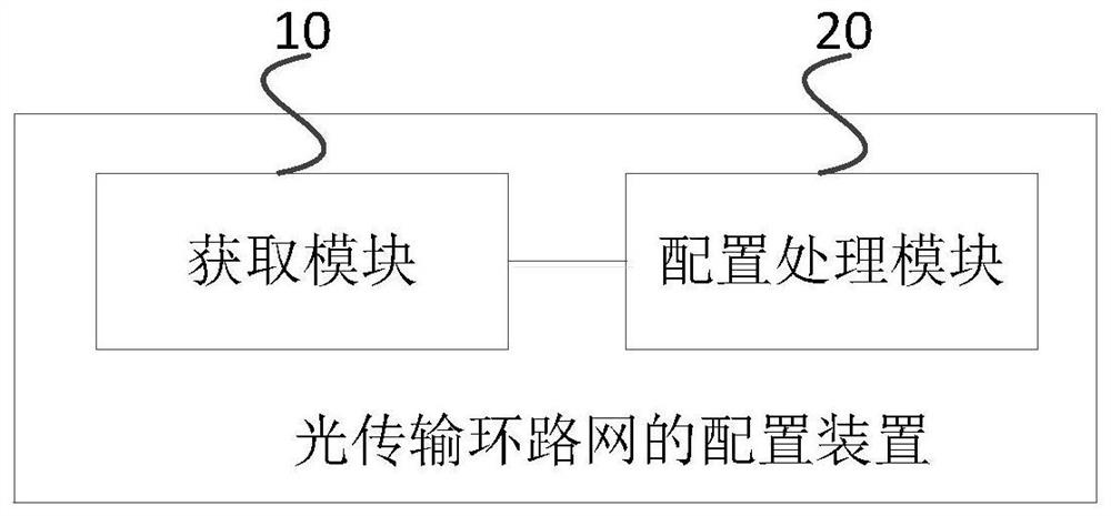
[0102] A configuration device corresponding to the channel of the optical transmission network of the present application, image 3 It is a schematic structural diagram of an optical transmission network channel configuration device provided in this application. For ease of illustration, only the parts relevant to the present application are shown.
[0103] refer to image 3 , the optical transmission network channel configuration device includes:
[0104] The obtaining module 10 is used to obtain the service estimated capacity of each optical transmission node on all ring networks and link networks of the optical transmission network;
[0105] The configuration processing module 20 is configured to perform channel configuration for the optical transmission ring network and the link network according to the service estimated capacity of each optical transmission node, to form a configured optical transmission network;
[0106] Wherein, in the configured optical transmission...
Embodiment 3
[0139] The electronic equipment provided by this application can be used to implement the technical solutions of the above method embodiments, Figure 4 It is a schematic diagram of the hardware structure of the electronic device provided by this application. For the convenience of description, only the parts related to this application are shown.
[0140] refer to Figure 4 , which shows a schematic structural diagram of an electronic device 1000 suitable for implementing the embodiment of the present application, and the electronic device 1000 may be a terminal device. Wherein, the terminal equipment may include but not limited to mobile phones, notebook computers, digital broadcast receivers, personal digital assistants (Personal Digital Assistant, PDA for short), tablet computers (Portable Android Device, PAD for short), portable multimedia players (Portable Media Player, PMP for short), mobile terminals such as vehicle-mounted equipment (such as vehicle-mounted navigatio...
PUM
 Abstract
Description
Claims
Application Information
 - R&D Engineer
- R&D Manager
- IP Professional
- Industry Leading Data Capabilities
- Powerful AI technology
- Patent DNA Extraction
Browse by: Latest US Patents, China's latest patents, Technical Efficacy Thesaurus, Application Domain, Technology Topic, Popular Technical Reports.
© 2024 PatSnap. All rights reserved.Legal|Privacy policy|Modern Slavery Act Transparency Statement|Sitemap|About US| Contact US: help@patsnap.com