
Stator paint dipping and drying device of permanent magnet motor

A drying device and permanent magnet motor technology, which is applied in electromechanical devices, manufacturing motor generators, electrical components, etc., can solve the problems of low utilization rate and difficult stator separation, so as to prolong the service life, speed up the drying rate, and reduce the damage effect

Pending Publication Date: 2022-02-11
江西东涵科技协同创新有限公司
View PDF0 Cites 1 Cited by
  • Summary
  • Abstract
  • Description
  • Claims
  • Application Information

AI Technical Summary

Problems solved by technology

[0003] The stator of the permanent magnet motor needs to be dried after being dipped in paint. In the prior art, the internal utilization rate of the stator drying device is small, so that the drying device can only dry a small number of stators at a time. In this regard, the drying efficiency of the stator drying device is relatively common, and when multiple stators are dried together, multiple stators will be glued together after drying due to the impregnated paint, making the stator The separation between them is relatively difficult, and the drying of the stator in the prior art usually adopts fixed-point drying, which also leads to some positions of the stator that have not been dried after drying and need to be re-dipped and dried again

Method used


Image

  • Stator paint dipping and drying device of permanent magnet motor
  • Stator paint dipping and drying device of permanent magnet motor
  • Stator paint dipping and drying device of permanent magnet motor

Examples


Embodiment Construction

[0050] In order to further understand the features, technical means, and specific objectives and functions achieved by the present invention, the present invention will be further described in detail below in conjunction with the accompanying drawings and specific embodiments.

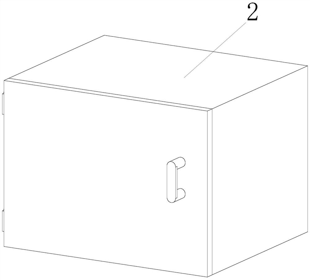
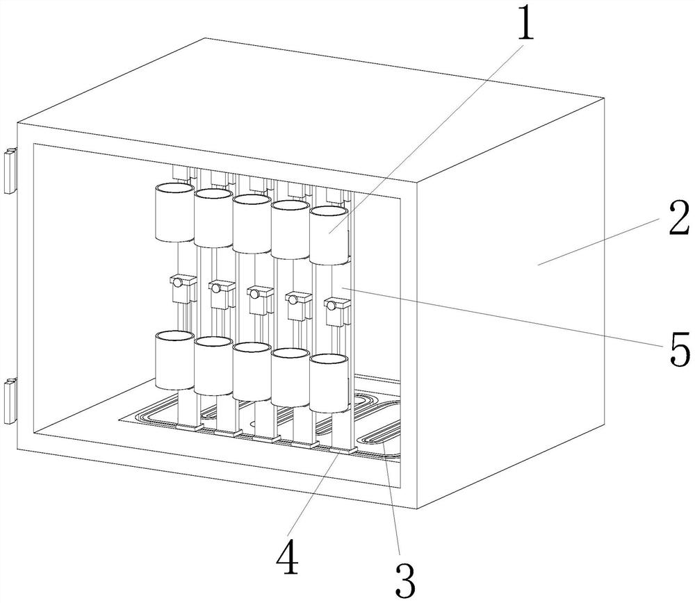
[0051] refer to Figure 1-12 shown

[0052] A stator dipping paint drying device for a permanent magnet motor,

[0053] The motor stator 1 is in the shape of a circular cylinder, and the drying device includes a drying box 2, a chain conveyor 3, a chain attachment 4 and a clamp 5; the chain conveyor 3 includes a chain 3a and a meshing wheel 3b;

[0054] Fixture 5 is equidistant and vertically installed on the top of chain conveyor 3 through chain attachment 4;

[0055] The chain 3a is used to drive the fixture 5 to move regularly inside the drying box 2;

[0056] The chain 3a is composed of a first transmission shaft 3a1 and a second transmission shaft 3a2, and the first transmission shaft 3a1 is be...


PUM


Abstract

The invention relates to the field of permanent magnet motor stator drying, in particular to a stator paint dipping and drying device of a permanent magnet motor. A motor stator is in an annular cylinder shape, and the drying device comprises a drying box, a chain type conveyor, chain accessories and clamps. The chain type conveyor comprises a chain and a meshing wheel; and the clamps are vertically installed on the top of the chain type conveyor at equal intervals through the chain accessories. After the motor stators are mounted on the clamps, the chain type conveyor is started to drive the clamps to regularly move in the drying box, so that the motor stators can be uniformly heated and dried, and the drying rate of the motor stators is increased; the internal space of the drying box can be well utilized through regular movement tracks to increase the drying number of the motor stators, and the motor stators cannot make contact with one another when the multiple motor stators are dried, so that the phenomenon that in the prior art, the motor stators are bonded together due to paint after drying, and are difficult to be seperated in the later period is prevented.

Description

technical field [0001] The invention relates to the field of stator drying of permanent magnet motors, in particular to a stator dipping and drying device for permanent magnet motors. Background technique [0002] The permanent magnet synchronous motor is mainly composed of a stator, a rotor and an end cover. The stator is made of laminations to reduce the iron loss generated during the operation of the motor. It is equipped with a three-phase AC winding, called an armature, and the rotor can be made The solid form can also be pressed by laminations, and permanent magnet materials are installed on it. According to the position of the permanent magnet material on the motor rotor, the offset permanent magnet synchronous motor can be divided into two types: protruding type and built-in type. form. [0003] The stator of the permanent magnet motor needs to be dried after being dipped in paint. In the prior art, the internal utilization rate of the stator drying device is small,...

Claims


Application Information

Patent Timeline
Patent Type & Authority Applications(China)
IPC IPC(8): H02K15/12
CPCH02K15/12
Inventor 赖诚明朱慧叶光友彭邦辉孙培淦
Owner 江西东涵科技协同创新有限公司
Learn More