
Backlight module, preparation process thereof and display device

A technology of backlight module and preparation process, which is applied in optics, nonlinear optics, instruments, etc., can solve problems such as excessive narrow frame defects, and achieve the effects of saving installation time, reducing narrow frames, and saving costs

Pending Publication Date: 2022-02-11
SHENZHEN SOUTH POLE OPTOELECTRONICS TECH
View PDF5 Cites 0 Cited by
  • Summary
  • Abstract
  • Description
  • Claims
  • Application Information

AI Technical Summary

Problems solved by technology

[0004] For example, the narrow frame of the backlight module commonly used in mobile phones has reached the limit, but compared with the OLED screen, the narrow frame of the mobile phone still has the defect of being too large

Method used


Image

  • Backlight module, preparation process thereof and display device
  • Backlight module, preparation process thereof and display device
  • Backlight module, preparation process thereof and display device

Examples


preparation example Construction

[0055] The working principle of the preparation process of the backlight module provided in this embodiment:

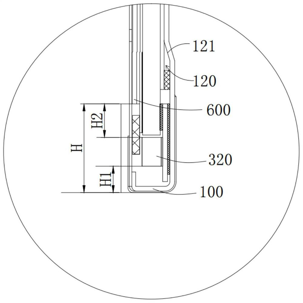
[0056] In the prior art, the FPC is installed on the plastic frame, and the plastic frame is embedded in the metal frame, wherein the metal frame, the plastic frame, the LED lamp and the light guide plate are arranged in sequence, and the FPC is located on the plastic frame, and the FPC occupies a certain width. Furthermore, the distance H2 between the LED light and the visible area is increased, and the FPC needs to bypass the LED light to connect to the motherboard, which will increase the distance H1 between the LED light and the metal frame tail frame to a certain extent, and the plastic frame is located between the LED light and the metal frame , which greatly increases the distance H1 between the LED lamp and the tail frame of the metal frame, thereby greatly increasing the distance H between the visible area and the tail frame of the metal frame.

[0057]Usuall...

Embodiment 1

[0094] S1, automatic feeding metal frame;

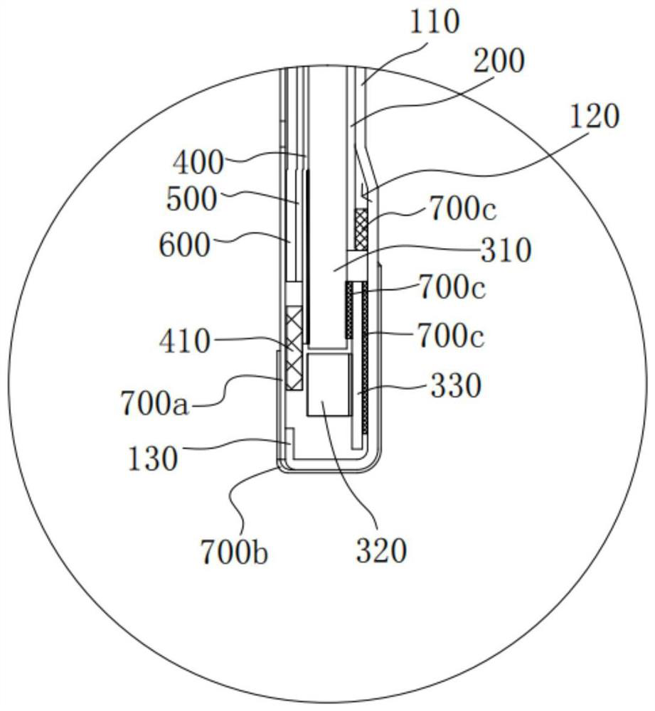
[0095] Specifically, the metal frame 100 includes a frame body 110 , a sinker 120 , and a U-shaped groove 130 . Before loading the metal frame 100 , the sinker 120 and the U-shaped groove 130 are processed on the metal frame 100 .

[0096] S2, paste reflective sheet;

[0097] S3. Insert the light guide plate assembly obliquely into the metal frame;

[0098] Specifically, the suction block sucks the light-emitting surface of the light guide plate 310, the suction block rotates 15 degrees, inserts the FPC light bar 300a obliquely into the corresponding sinker groove 120 in the metal frame 100, and then adjusts the position of the light guide plate 310 away from the FPC light bar 300a. Put it into the metal frame 100 at one end.

[0099] S4, paste diffusion film;

[0100] S5, paste the brightness enhancement film;

[0101] S6, affix the enhancement film;

[0102] S7, paste light-shielding glue;

[0103] S8, one-sided adhesive tape f...


PUM


Abstract

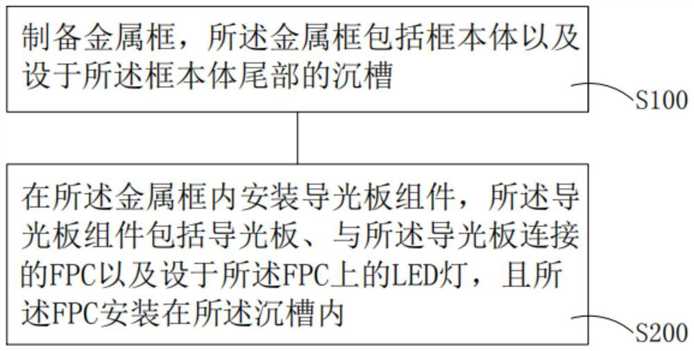
The invention discloses a backlight module, a preparation process thereof and a display device, and the preparation process comprises the steps that a metal frame which comprises a frame body and a sinking groove formed in the tail part of the frame body is prepared; a light guide plate assembly is installed in the metal frame, the light guide plate assembly comprises a light guide plate, an FPC connected with the light guide plate and an LED lamp arranged on the FPC, and the FPC is installed in the sinking groove. The narrow frame is small, the screen-to-body ratio is increased, and the visual effect is improved; the cost is low, the production efficiency is high, and the heat dissipation performance is good.

Description

technical field [0001] The present invention relates to the technical field of display devices, in particular to a backlight module, a manufacturing process thereof, and a display device. Background technique [0002] Narrow bezel technology is a higher-level development requirement after the basic development of liquid crystal display technology. Narrow bezel means that a larger viewing area can be obtained on a display surface of the same size and resolution. [0003] With the continuous development of LCD product technology, the competition in the liquid crystal display market is becoming increasingly fierce. Among them, the narrow frame of the liquid crystal display device can effectively increase the high screen ratio and improve the visual effect, especially to adapt to the large size of mobile display products in the existing market. screen trend. [0004] For example, the narrow frame of the backlight module commonly used in mobile phones has reached its limit. Howe...

Claims


Application Information

Patent Timeline
Patent Type & Authority Applications(China)
IPC IPC(8): G02F1/13357
CPCG02F1/133607G02F1/133605G02F1/133608G02F1/133628
Inventor 徐贤强饶巍巍姜发明潘连兴
Owner SHENZHEN SOUTH POLE OPTOELECTRONICS TECH
Learn More