A low-loss Schottky rectifier reflow soldering device

A technology of reflow soldering and rectifier tube, which is applied to electric heating devices, auxiliary devices, welding equipment, etc., can solve the problems of weak adjustment ability of fixed circuit board devices, inability to adapt to the fixed installation process of circuit boards, and energy waste of reflow soldering equipment. Achieve the effect of increasing the processing range, good bearing effect, and reducing energy waste

Active Publication Date: 2022-08-09
先之科半导体科技(东莞)有限公司
View PDF8 Cites 0 Cited by
  • Summary
  • Abstract
  • Description
  • Claims
  • Application Information

AI Technical Summary

Problems solved by technology

[0003] In the prior art, reflow soldering technology is often used to solder the Schottky rectifier to the circuit board, and the air or nitrogen is heated to a high enough temperature and then blown to the circuit board on which the components have been pasted, so that the Schottky rectifier The solder on the side melts and bonds with the main board to realize the welding operation of the Schottky rectifier tube and the circuit board. However, in the prior art, the unloading operation of the circuit board is very cumbersome, and it needs to be repeatedly driven on the guide rail before unloading. It is not conducive to the continuity of production; the loading and unloading time of the circuit board is long, which leads to the waste of energy inside the reflow soldering equipment; the device for fixing the circuit board is not strong in adjustment ability, which makes it unable to adapt to the fixed installation process of different types of circuit boards

Method used


Image

  • A low-loss Schottky rectifier reflow soldering device
  • A low-loss Schottky rectifier reflow soldering device
  • A low-loss Schottky rectifier reflow soldering device

Examples


Embodiment Construction

[0036] In order to further understand the features, technical means, and specific goals and functions of the present invention, the present invention will be described in further detail below with reference to the accompanying drawings and specific embodiments.

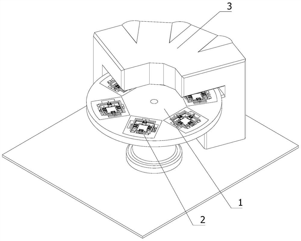
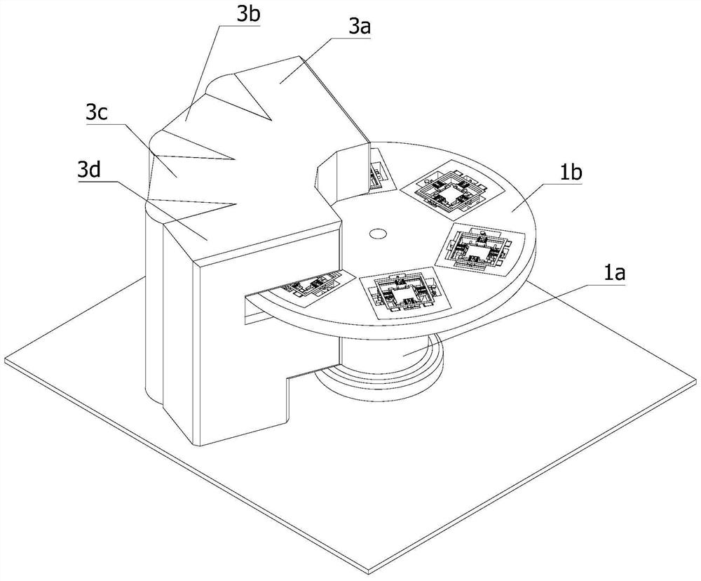
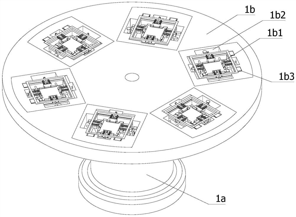
[0037] like Figure 1-4 shown:

[0038] A reflow soldering device for a low-loss Schottky rectifier tube includes a circuit board, a frame and a continuous conveying mechanism 1, a positioning and clamping mechanism 2 and a reflow welding mechanism 3 located above the frame, and the continuous conveying mechanism 1 It is fixedly installed on the frame, the reflow soldering mechanism 3 is arranged on the frame, and the continuous conveying mechanism 1 includes a turntable 1a and a working platform 1b. The working platform 1b is fixedly installed on the turntable 1a horizontally. In the through-mounting opening 1b1 of the positioning and clamping mechanism 2, several through-mounting openings 1b1 are annularly distribu...


PUM


Abstract

The invention relates to the field of Schottky rectifier tube welding, in particular to a reflow soldering device for a low-loss Schottky rectifier tube, comprising a frame and a continuous conveying mechanism, a positioning clamping mechanism and a reflow welding mechanism located above the frame , The continuous conveying mechanism includes a turntable and a working platform. The working platform is provided with a number of through installation ports for installing the positioning and clamping mechanism. The reflow soldering mechanism includes a preheating component, a constant temperature component, a reflow soldering component and a cooling component. The clamping mechanism includes an installation frame, a bearing component and a clamping component, the bearing component is horizontally arranged on the installation frame, the clamping component is arranged above the bearing component, and one side of the clamping component is hinged with the top end of the bearing component. The application realizes continuous and uninterrupted welding operation, reduces the possibility of energy waste, and can also realize the precise clamping function of circuit boards of different types and sizes through the positioning and clamping mechanism, thereby improving the processing range of the equipment.

Description

technical field [0001] The invention relates to the field of Schottky rectifier tube welding, in particular to a low-loss Schottky rectifier tube reflow soldering device. Background technique [0002] The Schottky rectifier is also a Schottky diode. The Schottky diode is a precious metal (gold, silver, aluminum, platinum, etc.) A as the positive electrode, and an N-type semiconductor B as the negative electrode, using the potential barrier formed on the contact surface of the two. Metal-semiconductor devices made with rectifying properties. Because there are a large number of electrons in N-type semiconductors and only a very small amount of free electrons in noble metals, electrons diffuse from B with high concentration to A with low concentration. Obviously, there are no holes in metal A, so there is no diffusion movement of holes from A to B. With the continuous diffusion of electrons from B to A, the electron concentration on the surface of B gradually decreases, and t...

Claims


Application Information

Patent Timeline
Patent Type & Authority Patents(China)
IPC IPC(8): B23K3/00B23K3/04B23K3/08H05K3/36B23K101/42
CPCB23K3/00B23K3/04B23K3/08B23K3/085B23K3/087H05K3/363H05K2201/09372B23K2101/42
Inventor 许卫林
Owner 先之科半导体科技(东莞)有限公司
Why Eureka
Try Eureka