
Method for determining dynamic change of pressure gradient to be started after heavy oil water drive is converted into hot water drive

A start-up pressure gradient and dynamic change technology, applied in the measurement of fluid pressure, pressure difference measurement between multiple valves, earthwork drilling and production, etc., can solve few problems

Pending Publication Date: 2022-02-08
CHINA NAT OFFSHORE OIL CORP +1
View PDF0 Cites 0 Cited by
  • Summary
  • Abstract
  • Description
  • Claims
  • Application Information

AI Technical Summary

Problems solved by technology

[0012] The published papers such as "Determination of Reasonable Injection-Production Well Spacing in the Existence of Threshold Pressure Gradient" mainly focus on experimental tests or numerical simulations under constant temperature conditions, and consider the impact of injection temperature on geological reservoir parameters (such as crude oil viscosity, permeability, etc.) rate, etc.), through the analysis of geological reservoir parameter changes under high temperature conditions, there are few studies on the quantitative analysis of the dynamic changes of the quasi-threshold pressure gradient in the hot water flooding process.

Method used


Image

  • Method for determining dynamic change of pressure gradient to be started after heavy oil water drive is converted into hot water drive
  • Method for determining dynamic change of pressure gradient to be started after heavy oil water drive is converted into hot water drive
  • Method for determining dynamic change of pressure gradient to be started after heavy oil water drive is converted into hot water drive

Examples


Embodiment Construction

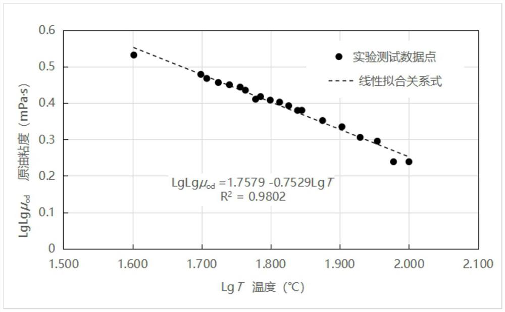
[0075] In order to better understand the purpose, structure and function of the present invention, a method for determining the dynamic change of the pseudo-starting pressure gradient of the heavy oil water flooding and then the hot water flooding of the present invention will be further described in detail below in conjunction with the accompanying drawings.

[0076] Such as Figure 1-Figure 9 Shown, the present invention mainly comprises the following steps:

[0077] Such as figure 1 As shown, the first step is to collect the static data of the geological reservoir in the target block;

[0078] Collect static data of geological reservoirs such as the effective thickness, permeability, porosity, and viscosity of crude oil in the target block;

[0079] The second step is to determine the relationship between the viscosity and temperature of the oil sample in the target block;

[0080] ⑴Collect crude oil samples from the target block and remove dissolved gas;

[0081] (2) T...


PUM


Abstract

The invention discloses a method for determining dynamic change of a pressure gradient to be started after heavy oil water drive is converted into hot water drive. The method comprises the following steps: 1, collecting geological reservoir static data of a target block; 2, determining a relational expression of oil sample viscosity and temperature of a target block; 3, testing the quasi-starting pressure gradients of the core and the oil sample of the target block under different temperature and permeability conditions; 4, obtaining a change relational expression of the starting pressure gradients at different temperatures along with the fluidity; 5, obtaining formation temperature field distribution of different stages of the hot water flooding process of the target block; 6, calculating a starting pressure gradient according to the geological reservoir parameters of each grid; and 7, drawing starting pressure gradient distribution diagrams of different stages of hot water drive of the target block. According to the method, the relational expressions of the quasi-starting pressure gradients, the permeability, the viscosity, the temperature and the like of the heavy oil reservoirs of different geological reservoir types are quantitatively represented; in addition, formation temperature field distribution of different stages of hot water injection flooding of the target block is obtained; and the production pressure difference and the limit well spacing of the target block are determined.

Description

technical field [0001] The invention belongs to the field of offshore petroleum engineering, and in particular relates to a method for determining the dynamic change of the proposed start-up pressure gradient after water flooding of heavy oil and water flooding. Background technique [0002] At present, the scale of heavy oil in the Bohai Sea is relatively large. For heavy oil reservoirs with a crude oil viscosity of about 150-400 mPa·s under formation conditions, conventional cold recovery such as natural energy and water injection is often used for development. As for the plane and interlayer conflicts, it can be basically solved through comprehensive adjustments such as plane well pattern adjustment and layered system development; however, due to the high viscosity of crude oil, the oil-water mobility in conventional water flooding is relatively large; and because the injected water The problem of easy breakthrough, resulting in low oil displacement efficiency and low swe...

Claims


Application Information

Patent Timeline
IPC IPC(8): G01N15/08G01L13/00E21B43/24
CPCG01N15/08G01N15/088G01L13/00E21B43/24
Inventor 胡廷惠刘东王传军郑旭冯海潮张洪朱琴郑双益王欣然李彪陈勇军
Owner CHINA NAT OFFSHORE OIL CORP
Learn More