Dynamic visualization observing device for displacement experiment

A technology of displacement experiment and observation device, which is applied in the direction of mining fluid, wellbore/well components, earthwork drilling and production, etc. It can solve problems that affect observation results, rock cores are not fixed, and it is difficult to form grooves, etc., so as to improve economic efficiency. Benefits, enhanced oil recovery, and convenient operation

Active Publication Date: 2016-03-23
CHINA UNIV OF PETROLEUM (BEIJING)
View PDF13 Cites 18 Cited by
  • Summary
  • Abstract
  • Description
  • Claims
  • Application Information

AI Technical Summary

Problems solved by technology

Although the glass model can simulate the distribution of oil and water during the displacement process, because the grooves are filled with core powder or quartz sand instead of real cores, the observation results do not conform to the real situation and cannot be used for guidance. Reservoir mining; the corroded grooves are irregular, even if the cores are placed in the grooves, the cores are not fixed and easy to move, which will lead to inaccurate observation results and serious errors; the model is made of glass, which is very difficult It is difficult to form a groove with the same size as the core, and it is difficult to ensure that the core is fixed, thus affecting the observation results

Method used


Image

  • Dynamic visualization observing device for displacement experiment
  • Dynamic visualization observing device for displacement experiment
  • Dynamic visualization observing device for displacement experiment

Examples


Embodiment 1

[0041] Such as figure 1 As shown, according to an embodiment of the dynamic visualization observation device for displacement experiments of the present invention, it includes a fluid pumping device 1, an intermediate piston container I2, an intermediate piston container II3, rock core slices 4 and a liquid collection container 5. The intermediate piston container I2 and the intermediate piston container II3 are connected in parallel between the fluid pumping device 1 and the core slice 4, and also include a dynamic visual microscopic model 6 and an observation component 7, and the core slice 4 is placed Inside the dynamic visualization micro-model 6 .

[0042] The rock core slices are fixed by a dynamic visualized microscopic model to simulate microscopic reservoir conditions. The middle piston container I is filled with oil, and the middle piston container II is filled with oil displacement system (water). The fluid pumping device is an advection pump. Inject oil from the...

Embodiment 2

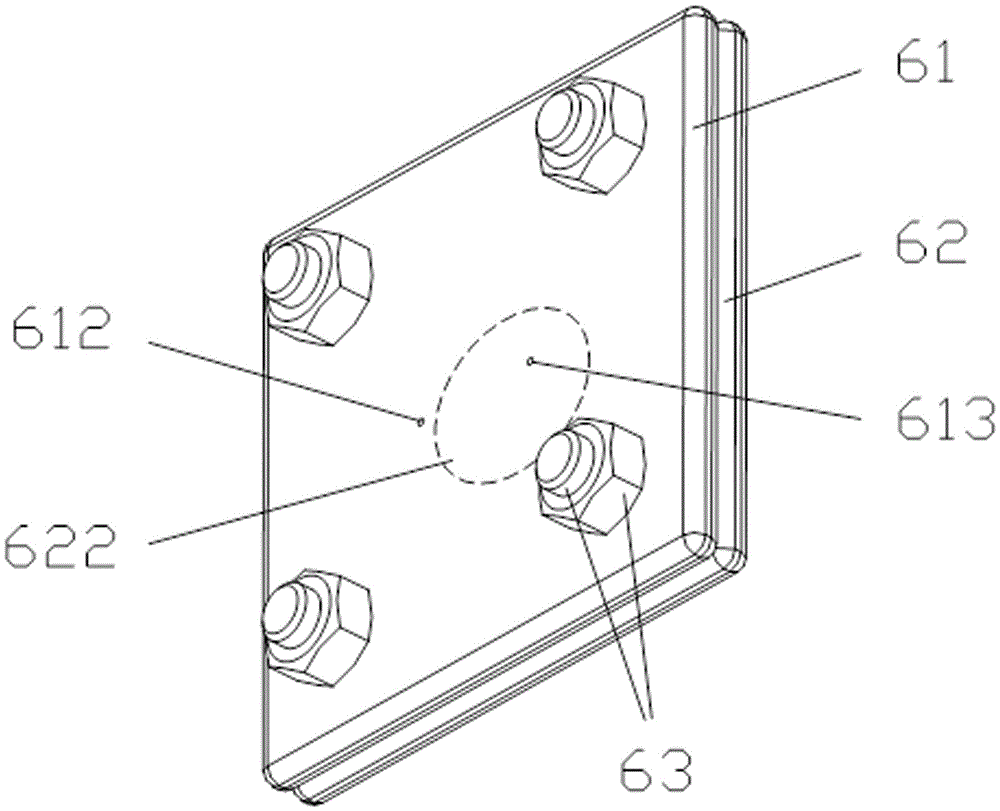
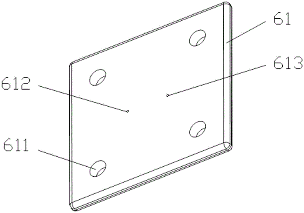
[0058] According to another embodiment of the dynamic visualization observation device for displacement experiments of the present invention, its structure, connection relationship between various components, working principle and beneficial effects, etc. are all the same as Embodiment 1, the difference is: The length of the body and the lower body of the model are both 150mm, the width is 150mm, and the thickness is 10mm. The diameter of the bolt hole of the upper body of the model and the lower body of the model is 15mm. The diameter of the oil-water injection port and the liquid discharge port are both 5mm, and the distance from the center of the upper body of the model is 20mm. After the core sheet is pressed and embedded, the groove formed in the center of the lower body of the model is circular in shape, with a diameter of 60mm and a depth of 0.1mm. The thickness of the core slices is 0.1mm.

[0059] The dynamic visual observation method used in the displacement experim...

Embodiment 3

[0061] According to another embodiment of the dynamic visualization observation device and method for displacement experiments of the present invention, its structure, process steps, working principle and beneficial effects are all the same as those of Embodiment 1, the difference is: After inserting the model lower body, directly use the model upper body to press on the rock core sheet until the model upper body and the model lower body are pressed together.


PUM

PropertyMeasurementUnit
Diameteraaaaaaaaaa
Diameteraaaaaaaaaa
Depthaaaaaaaaaa

Abstract

The invention relates to a dynamic visualization observing device for a displacement experiment. The dynamic visualization observing device comprises a fluid pumping-in device, a middle piston container I, a middle piston container II, a rock core slice, a fluid collecting container, a dynamic visualization micro model and an observing assembly. The middle piston container I and the middle piston container II are connected in parallel between the fluid pumping-in device and the rock core slice, and the rock core slice is arranged inside the dynamic visualization micro model. The dynamic visualization micro model is prepared from polydimethysiloxane, an oil and water injection opening and a liquid discharging opening are formed in the parts, with the equal distance to the center, on the two sides of the center of an upper model body respectively, the rock core slice is embedded in the center of a lower model body in a pressing mode, and thus a groove with the shape and dimension the same with those of the rock core slice is formed. The device is simple in structure and convenient to operate; the rock core slice is fixed by heating and softening the lower model body, the oil and water dynamic moving rules and distribution situations of different reservoir types are observed through different rock core slices, and then schemes for exploiting oil pools and increasing the oil recovery are made in a targeted mode.

Description

technical field [0001] The invention belongs to the technical field of oil reservoir exploitation, and in particular relates to a dynamic visualization observation device for displacement experiments. Background technique [0002] At present, the laboratory experiments on reservoir development are mainly fluidity experiments, which can test parameters such as the permeability and recovery factor of rock cores. The microscopic methods used in the experiments can statically observe the static state before or after displacement. oil-water distribution. However, fluidity experiments and microscopic methods cannot dynamically observe the migration and distribution of oil and water (water: generally refers to the oil displacement system) during the displacement process. If the law of oil-water migration in the displacement process can be grasped, and its migration channels and oil-water distribution can be clarified, it will be helpful to propose a targeted oil reservoir recovery...

Claims


Application Information

Patent Timeline
IPC IPC(8): E21B47/002E21B43/20
CPCE21B43/20E21B47/002
Inventor 李宜强孙晨崔洺珲
Owner CHINA UNIV OF PETROLEUM (BEIJING)
Why Eureka
Try Eureka