Coded disc and laser radar fused odometer method and mapping method
A lidar and odometer technology, applied in computing, image analysis, image data processing, etc., can solve problems such as easy failure, and achieve the effect of low drift rate
- Summary
- Abstract
- Description
- Claims
- Application Information
AI Technical Summary
Problems solved by technology
Method used
Image
Examples
Embodiment 1
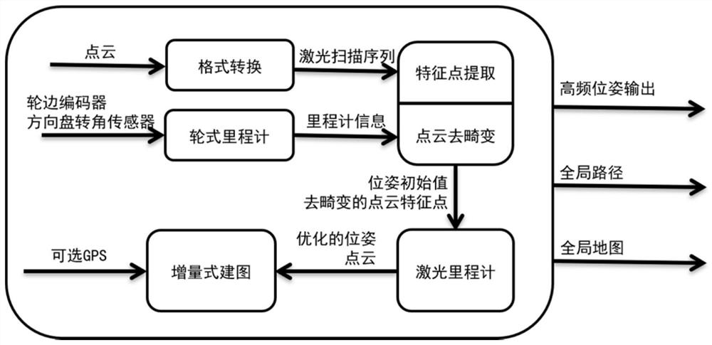
[0049] This embodiment provides an odometer method that integrates code discs and laser radars. Refer to figure 1 As shown, the method includes the following steps: collect the data of the wheel encoder and the steering wheel angle sensor, obtain the wheel odometer information based on the Ackermann steering geometry; obtain the point cloud data through the lidar, convert the format of the point cloud data, and obtain A laser scanning sequence; performing dedistortion and feature point extraction on the laser scanning sequence; performing pose optimization based on the extracted feature points to obtain a final high-frequency pose output.
Embodiment 2
[0051] Such as figure 1As shown, this embodiment provides an online mapping method, which is implemented based on a three-layer SLAM framework. In this framework, the first layer introduces the wheel odometry method based on Ackerman steering geometry, which outputs high-frequency motion in real time for point cloud de-distortion and serves as the initial value for pose optimization; the second layer uses An improved feature-based two-stage method based on the angle metric extracts edge features, planar features and degenerated features from point clouds, processes features at local scan scale and local map scale respectively to obtain more stable feature extraction results, and then The feature is analyzed, and the constraints on the sensor attitude are formed in the form of frame-local map, which is used for LiDAR odometry optimization; in the third layer, a graph-based method is applied to construct a model with LiDAR odometry factor, loop closure factor and optional GPS fa...
Embodiment 3
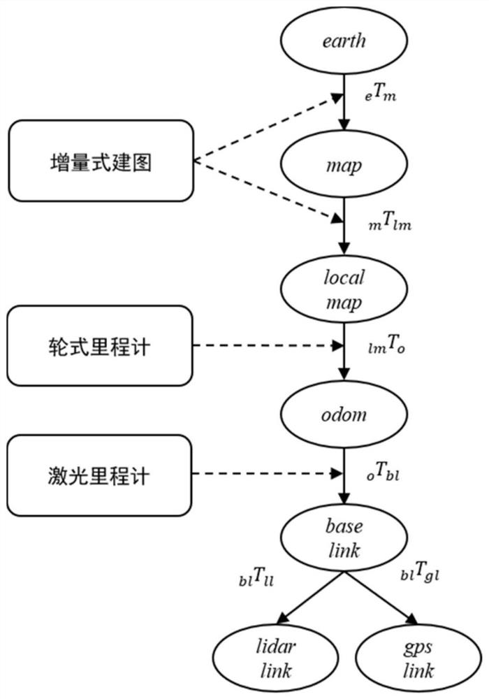
[0053] This embodiment provides a SLAM (simultaneous localization and mapping, synchronous localization and mapping) system WLAOM, which utilizes different sensors for real-time odometer and online map drawing; the improved feature-based LiDAR odometer method passes the wheel based on kinematics model The odometry method is enhanced to produce low-latency, low-drift attitude estimates, using a factor graph-based approach to fuse loop closure detection and GPS measurements, where self-aligning GPS factors are modeled to correct for attitude and estimate the relationship between GPS and local coordinate systems. transformation relationship between them. This allows the system to map vast areas covering many kilometers.
[0054] The system consists of five modules, receiving point cloud data directly from LiDAR and encoder data, and optional GPS measurement data via CAN, the system outputs optimized global trajectory and global point cloud map, both of which are compatible with G...
PUM
 Abstract
Description
Claims
Application Information
 - Generate Ideas
- Intellectual Property
- Life Sciences
- Materials
- Tech Scout
- Unparalleled Data Quality
- Higher Quality Content
- 60% Fewer Hallucinations
Browse by: Latest US Patents, China's latest patents, Technical Efficacy Thesaurus, Application Domain, Technology Topic, Popular Technical Reports.
© 2025 PatSnap. All rights reserved.Legal|Privacy policy|Modern Slavery Act Transparency Statement|Sitemap|About US| Contact US: help@patsnap.com


