Efficient driving method and device of mini LED

An LED driving and high-efficiency driving technology, applied in the use of semiconductor lamps, electrical components, energy-saving control technology, etc., can solve the problems of poor applicability and low efficiency of MiniLED, and achieve the effect of improving accuracy, high driving efficiency and improving efficiency.

Pending Publication Date: 2022-02-01
NEW VISION MICROELECTRONICS INC
View PDF0 Cites 0 Cited by
  • Summary
  • Abstract
  • Description
  • Claims
  • Application Information

AI Technical Summary

Problems solved by technology

[0007] Its driving circuit still adopts the traditional way, only through the adjustment of color temperature to ensure that the color temperature and brightness of the LED can be controlled, but there are still many problems of low efficiency and poor applicability when it is applied to Mini LED

Method used


Image

  • Efficient driving method and device of mini LED
  • Efficient driving method and device of mini LED
  • Efficient driving method and device of mini LED

Examples


Embodiment 1

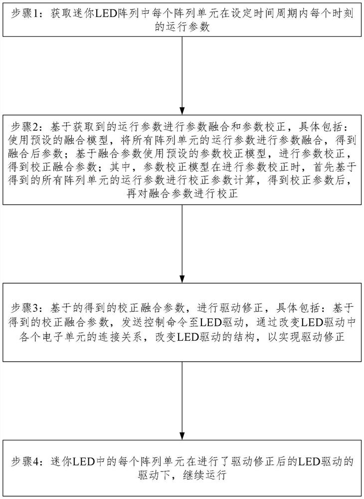
[0036] like figure 1 As shown, a highly efficient driving method for mini LEDs, the method performs the following steps:

[0037] Step 1: Obtain the operating parameters of each array unit in the mini LED array at each moment within the set time period;

[0038] Step 2: Perform parameter fusion and parameter correction based on the obtained operating parameters, specifically including: using the preset fusion model, performing parameter fusion on the operating parameters of all array units to obtain the fused parameters; using the preset parameters based on the fused parameters Correcting the model to perform parameter correction to obtain corrected fusion parameters; wherein, when performing parameter correction, the parameter correction model first calculates the corrected parameters based on the obtained operating parameters of all array units, and then corrects the fusion parameters after obtaining the corrected parameters;

[0039] Step 3: Carry out driver correction bas...

Embodiment 2

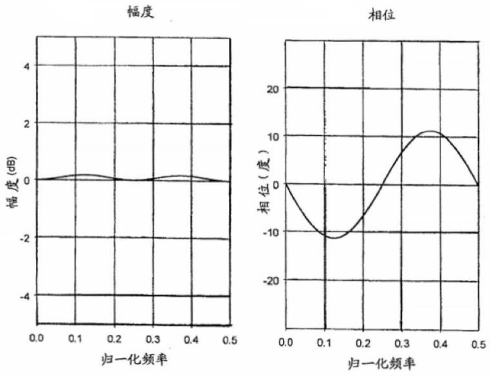
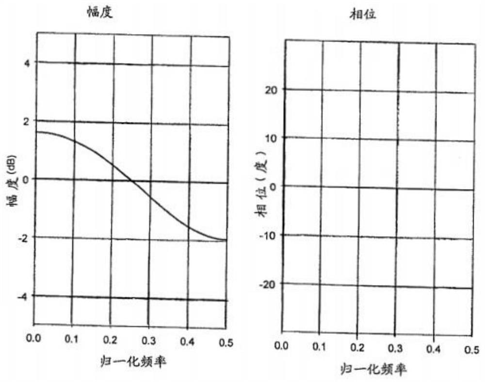
[0044] On the basis of the previous embodiment, the operating parameters include: the amplitude, phase and frequency of infrared waves radiated by the array unit during operation.

Embodiment 3

[0046] On the basis of the previous embodiment, in the step 2, the fusion model is represented by the following formula: Among them, N is the number of array units in the mini LED array, A i The amplitude of the infrared wave radiated by each array element, W i is the phase of the infrared wave radiated by each array element, f i is the frequency of the infrared wave radiated by each array unit, η is the fusion correction function, which is a set arbitrary quadratic function; S is the obtained fusion parameter.

[0047] Specifically, with the increasing complexity of the system, it is obvious that relying on a single sensor to monitor physical quantities has many limitations. Therefore, in the fault diagnosis system, multi-sensor technology is used to monitor various characteristic quantities (such as vibration, temperature, pressure, flow, etc.), and the information of these sensors is fused to improve the accuracy and reliability of fault location. In addition, manual ob...


PUM


Abstract

The invention belongs to the technical field of LEDs, and particularly relates to an efficient driving method and device of a mini LED. The method comprises the following steps that: step 1, operation parameters of each array unit in the mini LED array at each moment in a set time period are obtained; and step 2, parameter fusion and parameter correction are carried out based on the obtained operation parameters; specifically, a preset fusion model is used for carrying out parameter fusion on the operation parameters of all the array units, and fused parameters are obtained; and based on the fusion parameter, a preset parameter correction model is used to perform parameter correction to obtain a corrected fusion parameter. According to the method, various parameters of the infrared waveform of each array unit in the mini LED array during operation are acquired, parameter fusion and correction are performed, and then driving correction is performed, so that the adaptability of LED driving can be remarkably improved, and meanwhile, the driving efficiency is improved.

Description

technical field [0001] The invention belongs to the technical field of LEDs, and in particular relates to an efficient driving method and device for miniature LEDs. Background technique [0002] Mini LED refers to LED chips with a size on the order of 100 microns. The size is between small-pitch LEDs and Micro LEDs. It is the result of further refinement of small-pitch LEDs. Among them, small-pitch LED refers to LED backlight or display products with a pitch of adjacent lamp beads below 2.5 mm. [0003] Micro LED, Mini LED and OLED are all active self-luminous displays with high light utilization. The LCD is a passive light-emitting display that requires a backlight to provide a light source. Mini LED is compared with the current mainstream display technology LCD. Mini LED has a better display effect, and the response speed has been improved by an order of magnitude. The screen can be thinner and lighter, and the power consumption is greatly reduced. [0004] LED is a se...

Claims


Application Information

Patent Timeline
Patent Type & Authority Applications(China)
IPC IPC(8): H05B45/30H05B45/10H05B45/14
CPCH05B45/30H05B45/10H05B45/14Y02B20/30Y02B20/40
Inventor 肖宏
Owner NEW VISION MICROELECTRONICS INC
Why Eureka
Try Eureka