Rapid butt joint device for insulating rod
A technology of a docking device and an insulating rod, which is applied in the direction of an insulator and the like, can solve the problems that the unlocking operation is not convenient and fast, the connection between the rod and the rod is not fast enough, and the unlocking of the device is difficult, and the effect of simple structure, convenient portability or storage, and low cost is achieved.
- Summary
- Abstract
- Description
- Claims
- Application Information
AI Technical Summary
Problems solved by technology
Method used
Image
Examples
Embodiment 1
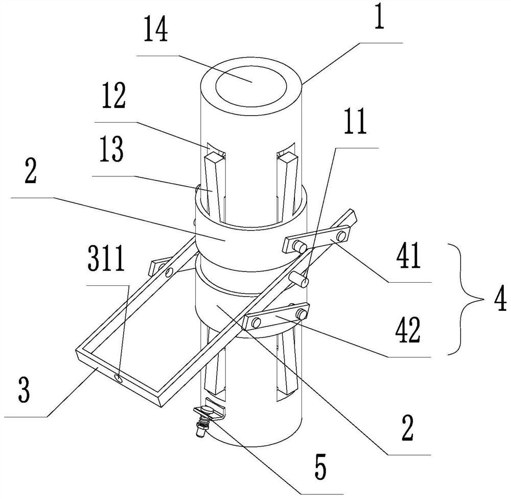
[0033] Example 1: See Figure 1-5 ;
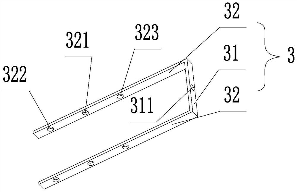
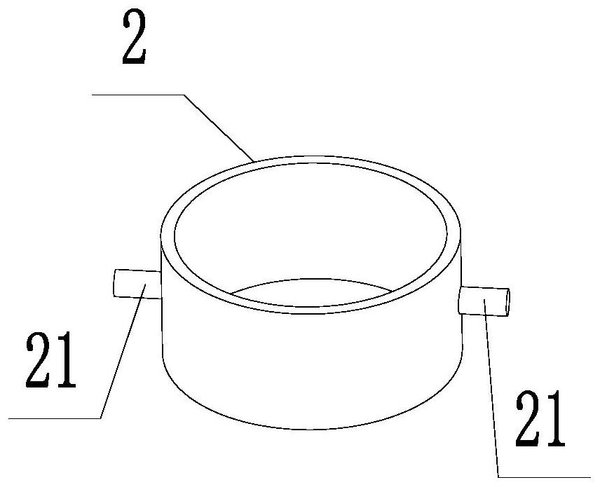
[0034] The present invention provides the following technical solutions: a quick butt joint device for insulating rods, comprising a pipe body 1, a sliding sleeve 2, a door-shaped switch knife 3, a scissor link assembly 4 and a limit pin assembly 5;
[0035] The pipe body 1 is in the shape of a cylindrical tube with a circular through hole 14 in the center, and the middle part of the side is symmetrically fixedly welded with the first rotating shaft 11, and the side is provided with a plurality of slots 12, and the plurality of slots 12 are divided into two groups , 4 in each group, evenly distributed around the axis of the tube body 1, two groups of slots 12 are symmetrically arranged up and down centered on the rotating shaft 11, each slot 12 is provided with an elastic card 13, and one end of the elastic card 13 close to the rotating shaft 11 can be The elastic deformation is fixedly connected to the tube body 1, and the inner side of ...
Embodiment 2
[0050] Example 2: see Image 6 ;
[0051] A quick butt joint device for insulating rods, the difference from Embodiment 1 is that the scissor link assembly 4 also includes a third connecting plate 43, a fourth connecting plate 44, a fifth connecting plate 45 and a sixth connecting plate 46; and the protrusion 131 is made of elastic rubber material;
[0052] The end of the third connecting plate 43 and the fourth connecting plate 44 are hinged, the other end of the third connecting plate 43 is hinged on the second rotating shaft 21 located on the upper sliding sleeve 2, and the other end of the fourth connecting plate 44 is hinged on the tube. On the first shaft 11 of the body 1; the end-to-end hinge of the fifth connecting plate 45 and the sixth connecting plate 46, the other end of the fifth connecting plate 45 is hinged on the second rotating shaft 21 located at the lower sliding sleeve 2, the sixth connecting plate The other end of 46 is hinged on the first rotating shaft...
PUM
 Abstract
Description
Claims
Application Information
 - R&D
- Intellectual Property
- Life Sciences
- Materials
- Tech Scout
- Unparalleled Data Quality
- Higher Quality Content
- 60% Fewer Hallucinations
Browse by: Latest US Patents, China's latest patents, Technical Efficacy Thesaurus, Application Domain, Technology Topic, Popular Technical Reports.
© 2025 PatSnap. All rights reserved.Legal|Privacy policy|Modern Slavery Act Transparency Statement|Sitemap|About US| Contact US: help@patsnap.com


