Device and method for selectively capturing and releasing charges in vacuum

A charge and vacuum technology, applied in the field of charge capture and release devices, can solve the problem of random charge on particles

Pending Publication Date: 2022-02-01
ZHEJIANG UNIV
View PDF0 Cites 1 Cited by
  • Summary
  • Abstract
  • Description
  • Claims
  • Application Information

AI Technical Summary

Problems solved by technology

The traditional method is to charge the particles by high-voltage discharge, but in this method, the charges on the particles are random

Method used


Image

  • Device and method for selectively capturing and releasing charges in vacuum

Examples


Embodiment Construction

[0027] The present invention will be described in further detail below in conjunction with the accompanying drawings and specific embodiments.

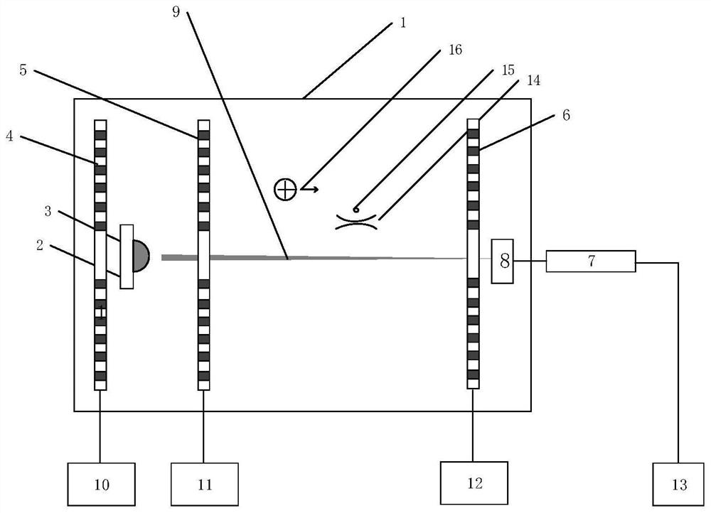
[0028] Such as figure 1 As shown, the device includes a vacuum chamber 1, a grid electrode system, a plasma system, an optical trap 14 and particles 15, the optical trap 14 and the particles 15 are located in the vacuum chamber 1, the particles 15 are stably trapped in the optical trap 14, and the optical trap 14 is formed by laser light generated by a light source outside the vacuum chamber 1 and focused into the vacuum chamber 1 by an optical fiber. The grid electrode system transports the charges 16 generated by the plasma system to the particles 15 .

[0029] The grid electrode system comprises a first grid electrode 4, a second grid electrode 5 and a third grid electrode 6, and the first grid electrode 4, the second grid electrode 5 and the third grid electrode 6 are parallel to each other in turn and The intervals are verticall...


PUM


Abstract

The invention discloses a device and a method for selectively capturing and releasing charges in vacuum. A light trap and particles are located in a vacuum chamber, the particles are stably captured in the light trap, and a grid electrode system conveys charges generated by a plasma system to the particles; the method comprises the steps that the plasma system emits and induces plasma laser to be vertically focused on the surface of a plasma target material and generate plasma, and the charges of the plasma are led out under the action of the grid electrode system, collide with the particles in the light trap in the one-way movement process and are selectively captured by the particles. Plasma is generated through laser induction, and a high-voltage electric field is prevented from being generated; meanwhile, by reasonably distributing the potential of the grid mesh electrode, the property and the electric quantity of charges moving in an electrostatic field are well controlled, so that the property of the charges captured by the particles is controlled.

Description

technical field [0001] The invention relates to a charge capture and release device, in particular to a charge selective capture and release device and method in vacuum. Background technique [0002] Optical tweezers are also called single-beam gradient optical traps. Since they were pioneered by American physicist Ashkin in the 1970s, optical tweezers control particles in a non-contact remote control method, which will not cause mechanical damage to the objects. Particles are tools that have been widely studied and applied in the fields of molecular biology, nanotechnology and experimental physics. [0003] The basic physical research of precision sensing based on vacuum optical trap technology often needs to establish the corresponding relationship between the particle photoelectric signal and the actual motion information (displacement) of the particle, that is, to establish the conversion relationship between the photovoltage signal and the particle displacement. The es...

Claims


Application Information

Patent Timeline
IPC IPC(8): G21K1/00
CPCG21K1/003
Inventor 刘承
Owner ZHEJIANG UNIV
Why Eureka
Try Eureka