
Fiber-optic gyroscope temperature drift compensation device and method based on multi-element temperature field

A technology of temperature drift and fiber optic gyroscope, which is applied in the direction of measuring device, Sagnac effect gyroscope, gyroscope/steering sensing equipment, etc. It can solve the problem of weak nonlinear regression ability, poor environmental adaptability, and the influence of non-temperature noise, etc. problem, to achieve the effect of accurate model, simple structure and high compensation accuracy

Active Publication Date: 2022-02-01
BEIHANG UNIV
View PDF6 Cites 0 Cited by
  • Summary
  • Abstract
  • Description
  • Claims
  • Application Information

AI Technical Summary

Problems solved by technology

The LSF model is simple and easy to implement in engineering, but the nonlinear regression ability is weak; the neural network modeling nonlinear approximation ability is strong, but the environmental adaptability is poor, and "over-fitting" phenomenon will occur; the SVM / SVR nonlinear approximation is strong, and it can Overcome the "overfitting" phenomenon and have good generalization ability, but are susceptible to non-temperature noise in the sample data

Method used


Image

  • Fiber-optic gyroscope temperature drift compensation device and method based on multi-element temperature field
  • Fiber-optic gyroscope temperature drift compensation device and method based on multi-element temperature field
  • Fiber-optic gyroscope temperature drift compensation device and method based on multi-element temperature field

Examples


Embodiment Construction

[0040] The present invention will be further described in detail below in conjunction with the accompanying drawings and embodiments. It can be understood that the specific implementation manners described here are only used to explain relevant content, rather than to limit the present invention. In addition, it should be noted that, for the convenience of description, only the parts related to the present invention are shown in the drawings.

[0041] It should be noted that, in the case of no conflict, the embodiments and features in the embodiments of the present invention can be combined with each other. The present invention will be described in detail below with reference to the drawings and in combination with embodiments.

[0042] In at least one embodiment of the present invention, the present invention provides an optical fiber gyro temperature drift compensation device and method based on a multivariate temperature field.

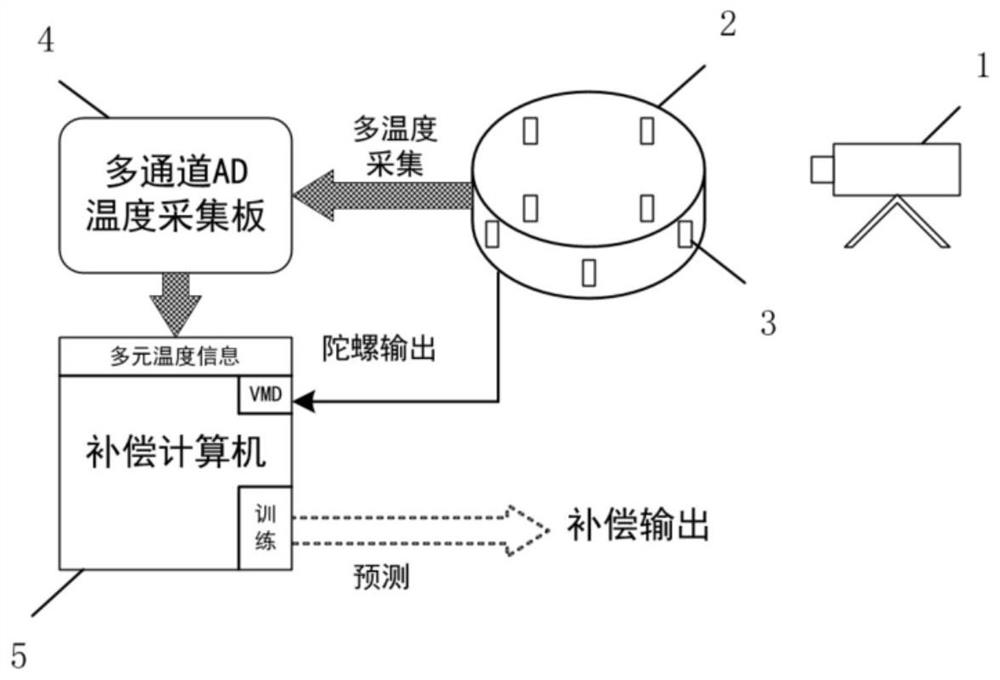
[0043] Such as figure 1 As shown, a fibe...


PUM


Abstract

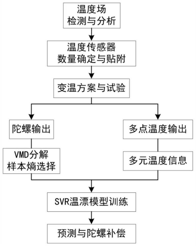
The invention provides a fiber-optic gyroscope temperature drift compensation device and method based on a multi-element temperature field. The fiber-optic gyroscope temperature drift compensation device comprises a thermal imager used for analyzing actual distribution of a fiber-optic gyroscope temperature field; a temperature sensor used for measuring the temperature of the optical fiber ring or the shell; a multichannel AD temperature acquisition board used for converting an analog signal into a digital signal and packaging and outputting the digital signal; and a compensation computer used for drift decomposition and multivariate temperature information calculation, and training, predicting and compensating a temperature drift model. The fiber-optic gyroscope temperature drift compensation method comprises the following steps: determining the number and attachment positions of temperature sensors according to temperature field distribution; obtaining gyroscopic drift, and extracting temperature drift by using variational mode decomposition (VMD); calculating multi-element temperature information including the temperature of the measuring points, the temperature change rate of the measuring points and the temperature gradient between the measuring points; and training a fiber-optic gyroscope temperature drift model based on the multi-element temperature information and SVM / SVR, and performing prediction and compensation output.

Description

technical field [0001] The invention belongs to the field of fiber optic gyroscopes, and relates to signal acquisition and digital processing methods, in particular to a temperature drift compensation device and method for fiber optic gyroscopes based on multiple temperature fields. Background technique [0002] Fiber optic gyroscope is a fiber optic ring inertial sensor based on the Sagnac effect. It has the characteristics of low cost, high reliability, wide dynamic range, and large development space. It is widely used in tactical weapons, aircraft, ships, and consumer markets. However, since the fiber optic gyroscope often works in harsh environments, the fiber optic loop is susceptible to non-reciprocity errors caused by the influence of the ambient temperature, resulting in gyro drift that is strongly related to temperature. [0003] Existing fiber optic gyroscope temperature drift and compensation methods include least quadratic fitting (LSF), a variety of neural netwo...

Claims


Application Information

Patent Timeline
IPC IPC(8): G01C19/72
CPCG01C19/721
Inventor 陈刚赵肖熙刘豪
Owner BEIHANG UNIV
Learn More