
Vibration mechanism and feeding device

A technology of vibrating mechanism and vibrating rod, applied in the direction of vibrating conveyors, conveyors, conveyor objects, etc., can solve the problems of difficulty in automatic feeding and high work intensity, and achieve automatic feeding operations and accurate feeding. Effect

Pending Publication Date: 2022-02-01
WENZHOU LUCHENG RIKANG SMOKING SETS FACTORY
View PDF7 Cites 3 Cited by
  • Summary
  • Abstract
  • Description
  • Claims
  • Application Information

AI Technical Summary

Problems solved by technology

[0003] Some small flake products with front and back sides have strict requirements on their correct placement in the process of processing, such as front side up or reverse side up. The feeding work for this kind of products is often done manually. material, it is difficult to realize automatic feeding, and the work intensity is high

Method used


Image

  • Vibration mechanism and feeding device
  • Vibration mechanism and feeding device
  • Vibration mechanism and feeding device

Examples


Embodiment Construction

[0026] Embodiments of the present invention will be further described below in conjunction with accompanying drawings:

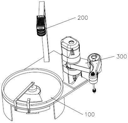
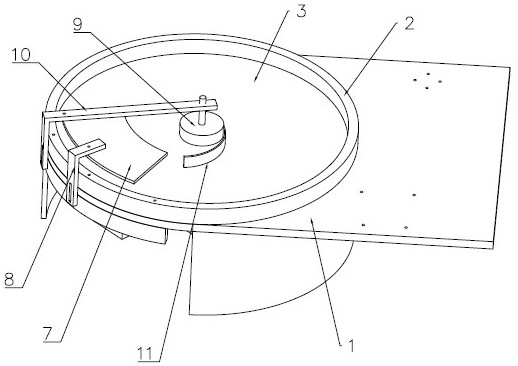
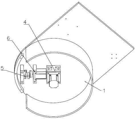
[0027] Such as figure 1 As shown, a feeding device includes a vibrating mechanism 100 , a visual inspection mechanism 200 , and a feeding robot 300 .

[0028] The vibrating mechanism 100 can disperse and turn over each product by vibrating, so that some products can be placed independently and in a specified direction (such as facing up).

[0029] The visual detection mechanism 200 can capture the image signal of the product in the vibration mechanism 100 by taking a camera, and then obtain the position of the product that is qualified and designated to face upward.

[0030] The loading robot 300 adopts a horizontal joint robot, which can accurately grab the corresponding product according to the information obtained by the visual inspection mechanism 200 and send it to the next process, so as to realize the purpose of automatic loading.

[0031] Both the ...


PUM


Abstract

The invention discloses a vibration mechanism and a feeding device. The vibration mechanism comprises a machine base, an annular check ring, a feeding disc, a first driving assembly, a vibration rod and a second driving assembly, the first driving assembly can drive the feeding disc to rotate in the annular check ring, and the second driving assembly can drive the vibration rod to achieve local vibration of the feeding disc. Through rotary feeding of the feeding disc and the local vibration effect, products can be continuously scattered and turned over and conveyed to the working range of the visual detection mechanism and the feeding robot, rapid and accurate feeding is achieved in cooperation with the visual detection mechanism and the feeding robot, and automatic feeding operation is achieved.

Description

technical field [0001] The invention relates to an automation device, in particular to a vibrating mechanism and a feeding device. Background technique [0002] How to realize the automatic feeding of products is an important part of realizing automatic production. [0003] Some small flake products with front and back sides have strict requirements on their correct placement in the process of processing, such as front side up or reverse side up. The feeding work for this kind of products is often done manually It is difficult to realize automatic feeding, and the work intensity is high. Contents of the invention [0004] In order to overcome the shortcomings of the background technology, the present invention provides a vibrating mechanism and a feeding device. [0005] The technical solution adopted in the present invention: a vibration mechanism, comprising [0006] Machine base; [0007] The annular retaining ring is fixedly installed on the machine base; [0008]...

Claims


Application Information

Patent Timeline
Patent Type & Authority Applications(China)
IPC IPC(8): B65G27/18B65G47/248B65G47/14B65G29/00B65G69/04
CPCB65G27/18B65G47/248B65G47/1421B65G29/00B65G69/0425B65G2203/041
Inventor 陈涵
Owner WENZHOU LUCHENG RIKANG SMOKING SETS FACTORY
Learn More