
Quantitative subpackaging device for balls

A quantitative sub-packaging, sphere technology, applied in packaging, solid materials, transportation and packaging, etc., can solve the problem of low efficiency of bearing steel ball sub-packaging, and achieve the effect of beautiful appearance, easy manufacturing, and improved sub-packaging efficiency.

Pending Publication Date: 2022-02-01
LUOYANG BEARING RES INST CO LTD
View PDF10 Cites 0 Cited by
  • Summary
  • Abstract
  • Description
  • Claims
  • Application Information

AI Technical Summary

Problems solved by technology

[0004] The object of the present invention is to provide a ball quantitative dispensing device to solve the technical problem of low efficiency of bearing steel ball dispensing in the prior art

Method used


Image

  • Quantitative subpackaging device for balls
  • Quantitative subpackaging device for balls
  • Quantitative subpackaging device for balls

Examples


Embodiment 1

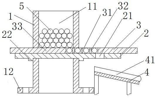
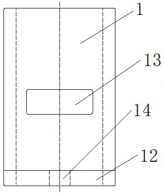
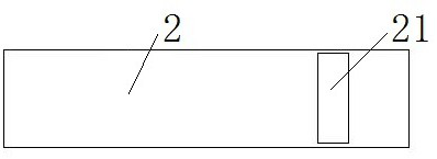
[0041] Such as figure 1 and figure 2 As shown, the sphere quantitative dispensing device includes a ball distribution seat 1 and a receiving platform 4, the ball distribution seat 1 is provided with a ball distribution cavity 11 for containing the spheroid 5, and the cavity wall of the ball distribution cavity 11 is equipped with a ball distribution plate 3 And the bottom support plate 2, the ball distribution plate 3 can translate on the bottom support plate 2. The bottom support plate 2 is provided with a leak ball hole 21, and the receiving platform 4 is located below the leak ball hole 21, and is used for receiving the ball 5 passing through the leak ball plate.

[0042] The sub-ball seat 1 is a cylindrical structure as a whole, arranged along the up and down direction, and its tube cavity forms a sub-ball cavity 11 for containing the sphere 5 . Two rectangular insertion holes 13 are arranged on the cavity wall of the cylinder cavity, and the two insertion holes 13 are ...

Embodiment 2

[0050] The difference between this embodiment and Embodiment 1 is that in Embodiment 1, the sub-ball seat 1 is a cylindrical structure, and the cylindrical cavity forms a sub-ball cavity 11 . However, in this embodiment, the ball distribution seat is a block structure, and a rectangular ball distribution chamber is arranged therein, and the distance between the bottom support plate and the wall of the ball distribution chamber is smaller than the diameter of the sphere.

Embodiment 3

[0052] The difference between this embodiment and Embodiment 1 is that in Embodiment 1, the bottom support plate 2 is only clamped on the sub-ball seat 1 by two clamping blocks 22 arranged at intervals. In this embodiment, connecting holes are provided at positions corresponding to the clamping block and the sub-ball seat, and the clamping block is connected to the sub-ball seat by inserting screws.


PUM


Abstract

The invention relates to a quantitative subpackaging device for balls. The device comprises a ball distributing seat, the ball distributing is provided with a ball distributing cavity for containing balls; a bottom supporting plate is arranged at the bottom of the ball distributing cavity, and two inserting holes which are oppositely formed are formed in the cavity wall of the ball distributing cavity, so that the ball distributing plate can penetrate through the inserting holes; the ball distributing plate is arranged above the bottom supporting plate and comprises a ball distributing area and a supporting area, and the two areas are distributed in the push-pull direction of the ball distributing plate; the ball distributing area is provided with a plurality of ball distributing holes, each ball distributing hole is only used for allowing one ball to enter, and after the ball distributing area completely enters the ball distributing cavity, the balls in the ball distributing cavity enter the ball distributing holes; and the supporting area is used for supporting the balls in the ball distributing cavity when the ball distributing area moves out of the ball distributing cavity. Compared with the prior art, manual number checking is not needed, and the subpackaging efficiency of the ball products is improved.

Description

technical field [0001] The invention relates to a sphere quantitative dispensing device. Background technique [0002] A fixed number of rolling steel balls are distributed between the inner and outer ring raceways of each set of ball bearings for load bearing and friction reduction. However, in the actual packing process of steel balls, it is difficult to realize mechanical automation. During manual packing, it takes a long time to count the balls and it is easy to cause missing packing, the packing efficiency is low, and the steel balls may be bumped and scratched. [0003] Therefore, it is necessary to design a device for quickly distributing balls, so as to quickly obtain the same number of balls and improve the dispensing efficiency. Contents of the invention [0004] The object of the present invention is to provide a ball quantitative dispensing device to solve the technical problem of low efficiency of bearing steel ball dispensing in the prior art. [0005] In o...

Claims


Application Information

Patent Timeline
Patent Type & Authority Applications(China)
IPC IPC(8): B65B1/30B65B1/04
CPCB65B1/30B65B1/04
Inventor 王梦茵郭培锐李凌鑫刘兢
Owner LUOYANG BEARING RES INST CO LTD
Learn More