Switch cabinet

A switch cabinet and cabinet body technology, applied in the field of switch cabinets, can solve the problems of temperature rise in electrical contact parts, no heat dissipation system, heat dissipation, etc., and achieve the effect of reducing fan power, good heat dissipation effect, and realizing temperature rise

Pending Publication Date: 2022-01-28
PINGGAO GRP
View PDF1 Cites 0 Cited by
  • Summary
  • Abstract
  • Description
  • Claims
  • Application Information

AI Technical Summary

Problems solved by technology

At present, there is no reasonable and effective heat dissipation system for the switchgear with the above arrangement. If the heat cannot be dissipated in time, the temperature of the electrical contact parts will rise, which will affect the normal use of the switchgear.

Method used


Image

  • Switch cabinet
  • Switch cabinet
  • Switch cabinet

Examples


Embodiment 1

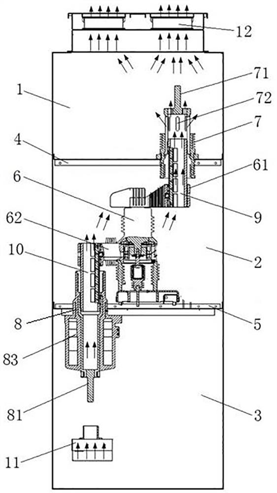
[0038] Such as figure 1 and figure 2 As shown, the switch cabinet includes a cabinet body, and the bus room 1, the circuit breaker room 2 and the cable room 3 are arranged in the cabinet in sequence from top to bottom. The bus room 1 and the circuit breaker room 2 are separated by an upper partition 4, and the circuit breaker The device chamber 2 and the cable chamber 3 are separated by a lower partition 5.

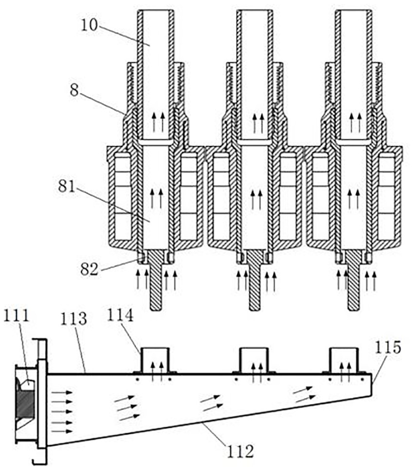
[0039] In this embodiment, the upper partition 4 is provided with an upper isolation sleeve 7, and the upper isolation sleeve 7 has an upper isolation static contact 71; the lower partition 5 is provided with a lower isolation sleeve 8, and the lower isolation sleeve 8 has Lower isolated static contact 81. Wherein, the upper isolating static contact 71 and the lower isolating static contact 81 are both hollow structures.

[0040] In this embodiment, a current transformer 83 is integrally formed on the lower isolating sleeve 8, which is designed in such a way that the ...

Embodiment 2

[0054] The difference between this embodiment and the first embodiment is that in the first embodiment, the heat dissipation fan includes an exhaust fan 12 and a blower 111 . In this embodiment, the cooling fan only includes a blower. In other embodiments, the cooling fan may only include a suction fan.

Embodiment 3

[0056] The difference between this embodiment and the first embodiment is that in the first embodiment, the air inlet channel is a wedge-shaped air channel. In this embodiment, the air inlet channel is a rectangular parallelepiped air channel.


PUM


Abstract

The invention relates to a switch cabinet. The switch cabinet comprises a cabinet body, a bus chamber, a circuit breaker chamber and a cable chamber are arranged in the cabinet body, the bus chamber and the circuit breaker chamber are separated through an upper partition plate, and an upper isolation static contact is arranged on the upper partition plate; the circuit breaker chamber and the cable chamber are separated through a lower partition plate, a lower isolation static contact is arranged on the lower partition plate, a solid-sealed polar pole is arranged in the circuit breaker chamber and provided with an upper wire outlet seat and a lower wire outlet seat, an upper isolation moving contact is installed on the upper wire outlet seat, a lower isolation moving contact is installed on the lower wire outlet seat, the upper isolation moving contact and the lower isolation moving contact are both of a vertically-through hollow structure, the lower isolation static contact is provided with a lower communicating hole communicating an inner cavity of the lower isolation static contact with the cable chamber, the upper isolation static contact is provided with an upper communicating hole communicating an inner cavity of the upper isolation static contact with the bus chamber, and the wall surface of the bus chamber is provided with an exhaust hole communicated with the inside and outside of the bus chamber; and the switch cabinet also comprises a heat dissipation fan which is used for enabling external cold air to enter the inner cavity of the lower isolation static contact through the lower communication hole.

Description

technical field [0001] The invention relates to a switch cabinet and belongs to the technical field of power distribution equipment. Background technique [0002] At present, some switch cabinets are arranged vertically inside, that is, the three-phase main circuit is arranged along the depth direction of the cabinet. For example, a switchgear disclosed in the Chinese patent document with the authorized announcement number CN103683016B takes the direction of the larger size of the switchgear in the horizontal direction as the front and rear direction, and the switchgear includes a busbar room, a circuit breaker room and a cable The busbar room and the circuit breaker room are separated by an upper partition, and three upper isolation sleeves are arranged at intervals along the front and rear directions on the upper partition, and the upper isolation sleeve has an upper isolation static contact; the circuit breaker room and the cable room Separated by the lower partition, th...

Claims


Application Information

Patent Timeline
Patent Type & Authority Applications(China)
IPC IPC(8): H02B1/56H02B1/32H02B1/30
CPCH02B1/565H02B1/32H02B1/30
Inventor 朱彦卿潘明祁海洋窦中萍张浩袁端磊王海燕朱志豪朱启媛
Owner PINGGAO GRP
Why Eureka
Try Eureka