
Liquid slag conveying system and method for liquid slag discharging boiler

A liquid slag discharge and conveying system technology, applied in the direction of combustion method, burner, combustion type, etc., can solve the problems of inability to heat, block, heat loss, etc., achieve automatic control, reasonable system design, and ensure stable operation Effect

Pending Publication Date: 2022-01-28
天津华能杨柳青热电有限责任公司 +1
View PDF0 Cites 0 Cited by
  • Summary
  • Abstract
  • Description
  • Claims
  • Application Information

AI Technical Summary

Problems solved by technology

Moreover, high-temperature molten ash has high utilization value. For example, a scheme and process for making glass fiber by using its high-temperature molten slag is proposed, and the high-temperature slag is transported to the glass fiber manufacturing equipment outside the slag hopper. The high-temperature slag flows out of the slag outlet from the granulation pool and is rapidly cooled to form slag particles, which causes a large amount of heat loss and lowers the overall energy utilization efficiency. Near the flow limit, the conventional slag diversion groove or slag chute is prone to poor flow of slag during the diversion process, blocking the slag diversion groove or slag chute, and it is difficult for the liquid slag to flow freely from the slag outlet to the glass in fiber manufacturing equipment
Therefore, it is necessary to heat the diversion groove or chute during this process, and the electrode heating method generally used needs to bury electrode wires in the diversion groove or chute, but because the diversion groove or chute required by the double U-shaped liquid slagging boiler Part of the chute needs to go deep into the slag well to receive high-temperature slag, and the internal temperature of the slag well is as high as 800 to 1000 °C, which cannot be tolerated by the electrode wires. Therefore, the conventional electrode heating guide trough cannot heat part of the guide trough in the slag well, and it is difficult to solve the problem of high temperature. The problem of poor flow of slag makes it impossible to realize the high value-added comprehensive utilization of high-temperature slag.

Method used


Image

  • Liquid slag conveying system and method for liquid slag discharging boiler
  • Liquid slag conveying system and method for liquid slag discharging boiler

Examples


Embodiment Construction

[0032] In order to make the purpose, technical solutions and advantages of the embodiments of the present invention clearer, the technical solutions in the embodiments of the present invention will be clearly and completely described below in conjunction with the drawings in the embodiments of the present invention. Obviously, the described embodiments It is a part of embodiments of the present invention, but not all embodiments. The components of the embodiments of the invention generally described and illustrated in the figures herein may be arranged and designed in a variety of different configurations.

[0033] Accordingly, the following detailed description of the embodiments of the invention provided in the accompanying drawings is not intended to limit the scope of the claimed invention, but merely represents selected embodiments of the invention. Based on the embodiments of the present invention, all other embodiments obtained by persons of ordinary skill in the art wi...


PUM


Abstract

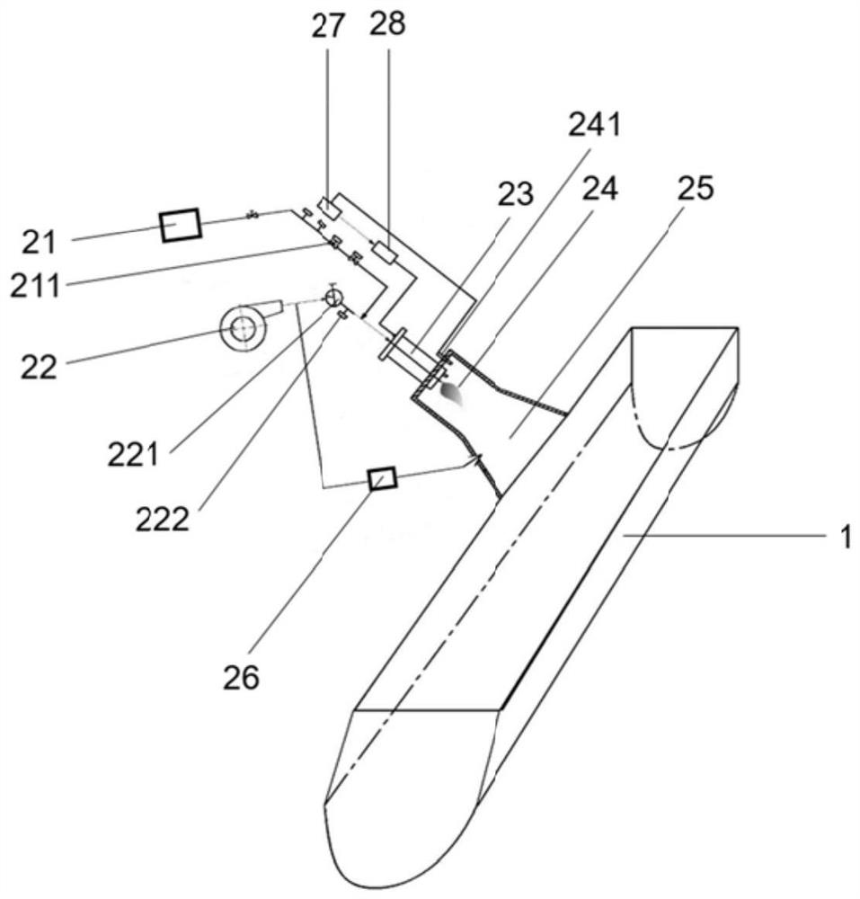
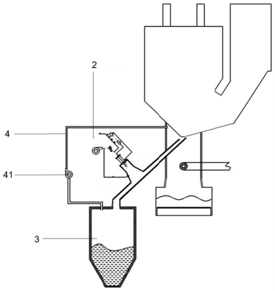
The invention discloses a liquid slag conveying system and method for a liquid slag discharging boiler. The system comprises a slag conveying groove and an auxiliary heating unit used for heating the slag conveying groove. The auxiliary heating unit comprises a combustible gas source, a combustion-supporting gas source, a combustor, a combustion chamber and a flue gas mixing chamber which are sequentially arranged in the transmission direction of combustible gas; one end of the slag conveying groove is communicated with a slag flowing opening of the slag discharging boiler, and the other end is connected with a downstream production line; and the side wall of the slag conveying groove is communicated with the flue gas mixing chamber. According to the system, the combustible gas is adopted as an auxiliary heat source to continuously heat the liquid slag flowing out of the slag flowing opening of the slag discharging boiler, so that the condition that the temperature of the slag flowing opening of the liquid slag discharging boiler is relatively low, the viscosity of the cooled high-temperature liquid slag is increased, and the slag flowing is unsmooth is effectively overcome, and high-added-value comprehensive utilization of the high-temperature slag is realized; the system is reasonable in design and convenient to operate.

Description

technical field [0001] The invention belongs to the technical field of boiler liquid slag treatment, and relates to a liquid slag conveying system and method for a liquid slag discharge boiler. Background technique [0002] The double U-shaped liquid slag removal boiler has the advantages of high furnace combustion temperature and long residence time. It uses the high furnace temperature to melt the coal-fired ash into a fluid form, and captures the ash in the flue gas through the slag-catching screen, making large Part of the ash and slag forms molten liquid slag and falls into the slag pool through the slag outlet at the bottom of the furnace, and uses the complete flue gas purification facilities of the coal-fired power station system to achieve ultra-low emission of tail flue gas, thereby achieving the goal of pulverized coal power plant boiler ash The purpose of volume reduction, volume reduction and harmless disposal of solid waste. Moreover, high-temperature molten a...

Claims


Application Information

Patent Timeline
Patent Type & Authority Applications(China)
IPC IPC(8): F23J1/08F23D14/02F23D14/60F23N5/00
CPCF23J1/08F23D14/02F23D14/60F23N5/00
Inventor 周昊邓月海马翔房凡赵怡吴连东汪华剑陈煜刘涛冯梅堂吴庆龙刘笑顾强强兆旺郝博宇王骏秦峰峰孙仲奎
Owner 天津华能杨柳青热电有限责任公司
Learn More