Low-noise air guide ring and fan comprising same
An air guide ring and low-noise technology, which is applied in the direction of mechanical equipment, machines/engines, liquid fuel engines, etc., can solve problems such as the inability to reduce the noise at the air outlet of the air guide ring, so as to avoid the increase of fan noise, facilitate manufacturing, and reduce The effect of eddy current noise
- Summary
- Abstract
- Description
- Claims
- Application Information
AI Technical Summary
Problems solved by technology
Method used
Image


Examples
Embodiment 1
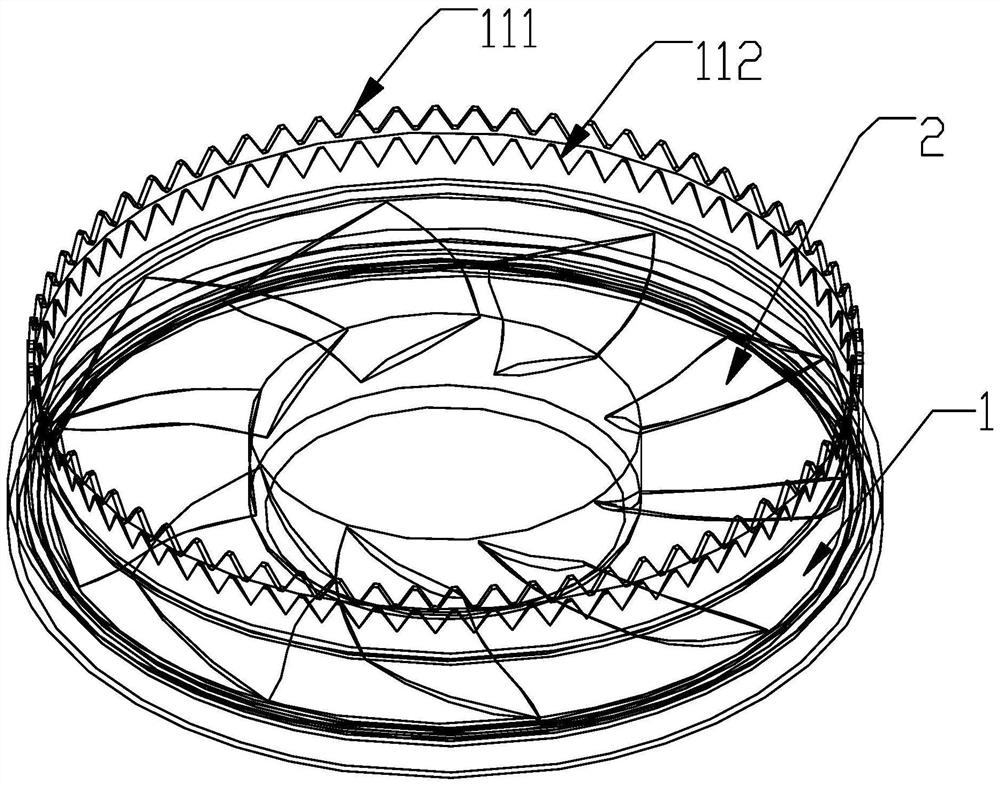
[0042] Such as figure 1 As shown, a low-noise wind guide ring 1, the air outlet of the wind guide ring 1 is provided with a multi-layer sawtooth noise reduction structure 11 distributed from the inner side of the wind guide ring 1 to the outside, and each layer of noise reduction structure includes There are several sawtooths, the sawtooth on the sawtooth noise reduction structure 11 extends along the axial direction of the wind guide ring 1 , and the thickness of the sawtooth noise reduction structure 11 gradually increases from the inside to the outside of the wind guide ring 1 . This setting makes the layers of the multi-layer sawtooth noise reduction structure 11 superimposed and arranged from the inside to the outside to form a multi-level noise reduction. The use of a multi-layer sawtooth bionic noise reduction structure at the air outlet of the air guide ring 1 can effectively reduce or delay the installation in the guide ring 1. The air flow generated by the rotation o...
Embodiment 2
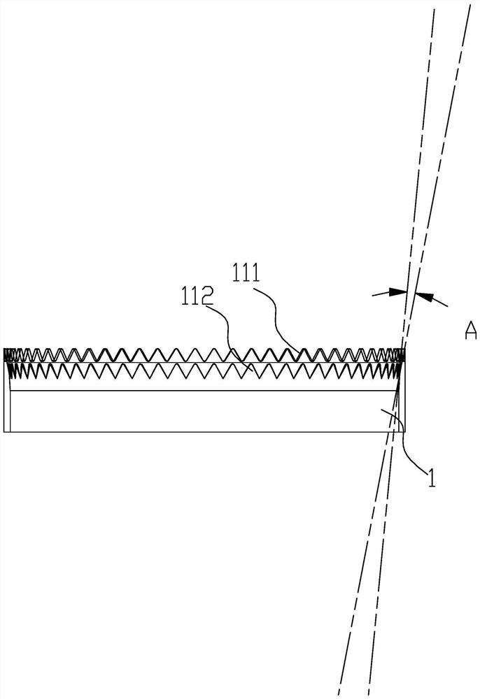
[0056] This embodiment only describes the differences from the above embodiments. In this embodiment, the sawtooth noise reduction structure 11 also includes an intermediate layer noise reduction structure located between the outer layer noise reduction structure 111 and the inner layer noise reduction structure 112. Noise structure, the middle layer noise reduction structure is provided with at least one layer. Specifically, the middle layer noise reduction structure is provided with one layer, and the sawtooth noise reduction structure 11 is provided with three layers in total. The sawtooth thickness is L1, the sawtooth height is h1, the sawtooth thickness of the second inner layer, that is, the middle layer noise reduction structure, is L2, and the sawtooth height is h2, and the third layer, that is, the inner layer noise reduction structure 112, has a sawtooth thickness of L3, and The height is h3, L1≧L2≧L3, h1≧h2≧h3; this setting can avoid the excessive thickness and heig...
Embodiment 3
[0058] Such as Figure 4 and 5 As shown, a fan includes a wind wheel 2, a guide vane bracket 3, a wind guide ring 1 and a motor 4, the motor 4 is connected to the wind wheel 2, and the outlet section of the wind guide ring 1 is close to the guide At the air outlet of the air guide ring 1, the inlet end of the air guide ring 1 is close to the air inlet of the air guide ring 1. It is characterized in that the guide vane bracket 3 is arranged at the outlet section of the air guide ring 1, The wind wheel 2 is arranged at the inlet section of the wind guide ring 1, and the wind guide ring 1 is the wind guide ring 1 described in any of the above-mentioned embodiments, and the innermost sawtooth between the wind wheel 2 and the wind guide ring 1 A transitional rectification section is provided between the tooth roots of the noise reduction structure 11, the height of the transitional rectification section is H2, the height of the wind wheel 2 is H1, H2≧0.2H1. This setting is becaus...
PUM
 Abstract
Description
Claims
Application Information
 - Generate Ideas
- Intellectual Property
- Life Sciences
- Materials
- Tech Scout
- Unparalleled Data Quality
- Higher Quality Content
- 60% Fewer Hallucinations
Browse by: Latest US Patents, China's latest patents, Technical Efficacy Thesaurus, Application Domain, Technology Topic, Popular Technical Reports.
© 2025 PatSnap. All rights reserved.Legal|Privacy policy|Modern Slavery Act Transparency Statement|Sitemap|About US| Contact US: help@patsnap.com