Fire-fighting smoke exhaust fan with high cooling speed and use method thereof
A technology of cooling speed and smoke exhaust fan, applied in separation methods, chemical instruments and methods, electromechanical devices, etc., can solve the problems of poor impurity removal effect, slow cooling speed of fire-fighting smoke exhaust fans, and low operating life of fans, etc. High exhaust air pressure, improve heat dissipation effect and heat dissipation rate, and reduce energy consumption
- Summary
- Abstract
- Description
- Claims
- Application Information
AI Technical Summary
Problems solved by technology
Method used
Image
Examples
Embodiment 1
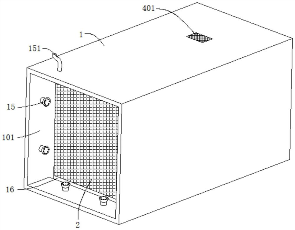
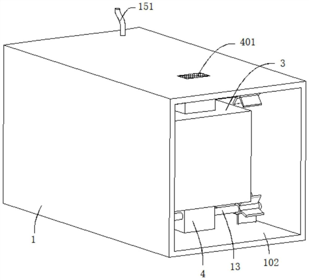
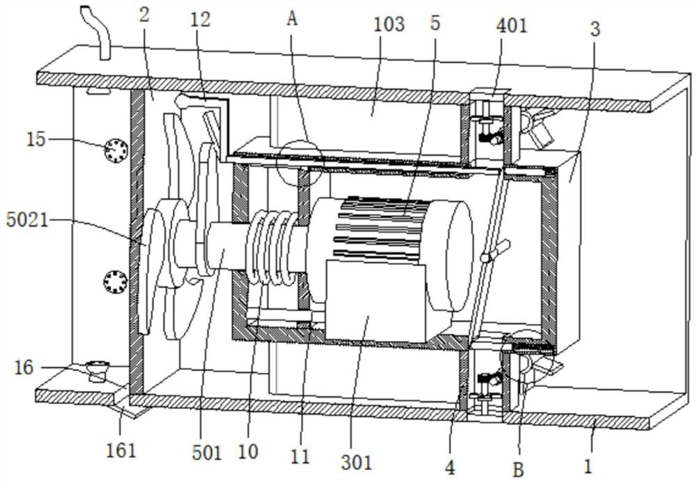
[0040] refer to figure 1 , figure 2 , image 3 , Figure 4 and Figure 8 , a fire-fighting smoke exhaust fan with fast cooling speed, comprising a fan cylinder 1, the two ends of the fan cylinder 1 are respectively provided with a smoke inlet 101 and a smoke outlet 102, the inner wall of the smoke inlet 101 is provided with a first filter screen 2, the fan The inner wall of the cylinder 1 is connected with a support plate 103, and the end of the support plate 103 away from the fan cylinder 1 is connected with the inner cylinder 3. The inner cylinder 3 is provided with a smoke exhaust assembly, and the inner cylinder 3 is also provided with an exhaust mechanism for heat dissipation. 3 The two sides of the outer wall are symmetrically connected with a heat dissipation air duct 4 matched with the exhaust mechanism, and a cooling mechanism for accelerating air flow is arranged in the heat dissipation air duct 4 , and a second filter screen 401 is connected to the inner wall of...
Embodiment 2
[0045] refer to image 3 , Figure 4 , Figure 5 , Figure 6 and Figure 7 , a fire-fighting smoke exhaust fan with fast cooling speed, which is basically the same as that of Embodiment 1. Further, the exhaust mechanism includes a fixed rod 302 fixedly connected to the inner wall of the inner cylinder 3, and the outer wall of the fixed rod 302 is rotatably connected to a rotating plate 6 , the two ends of the rotating plate 6 are movable against the inner wall of the heat dissipation air duct 4 on both sides of the inner cylinder 3 respectively, and both sides of the inner cylinder 3 are excavated with movable grooves 7, and the inner wall of the movable groove 7 is connected with a first elastic element 701. The end of the elastic element 701 away from the inner wall of the movable groove 7 is connected with a partition 702 , and the partition 702 is movable against the rotating plate 6 .
[0046] The exhaust mechanism also includes a sliding rod 8 that is slidably connec...
Embodiment 3
[0052] refer to figure 2 , image 3 , Figure 9 and Figure 10 , a fire-fighting smoke exhaust fan with a fast cooling rate, which is basically the same as that of Embodiment 2. Further, the cooling mechanism includes a first rotating rod 13 connected to the fan barrel 1 through a bearing, and the outer wall of the first rotating rod 13 is covered A sleeve 131 is connected, and the outer wall of the sleeve 131 is evenly distributed and connected with deflectors 132. The cooling mechanism also includes a second rotating rod 14 rotatably connected to the second filter screen 401, and the outer wall of the second rotating rod 14 is connected with a second fan. The disk 141 is connected with the second fan blade 142 on the outer wall of the second fan disk 141 , the worm wheel 143 is connected on the outer wall of the second rotating rod 14 , and the worm 133 meshing with the worm wheel 143 is connected on the outer wall of the first rotating rod 13 .
[0053] During use, the ...
PUM
 Abstract
Description
Claims
Application Information
 - R&D Engineer
- R&D Manager
- IP Professional
- Industry Leading Data Capabilities
- Powerful AI technology
- Patent DNA Extraction
Browse by: Latest US Patents, China's latest patents, Technical Efficacy Thesaurus, Application Domain, Technology Topic, Popular Technical Reports.
© 2024 PatSnap. All rights reserved.Legal|Privacy policy|Modern Slavery Act Transparency Statement|Sitemap|About US| Contact US: help@patsnap.com


