Protection type missile launching box and remote control weapon station
A technology of missile launch and protective box, which is applied in the field of remote control weapon stations, can solve the problems of not very beautiful, affecting product performance, and missiles not having bulletproof ability, so as to improve safety and reliability, fast loading and locking, good people The effect of machine performance
- Summary
- Abstract
- Description
- Claims
- Application Information
AI Technical Summary
Problems solved by technology
Method used
Image
Examples
Embodiment 1
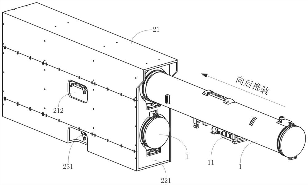
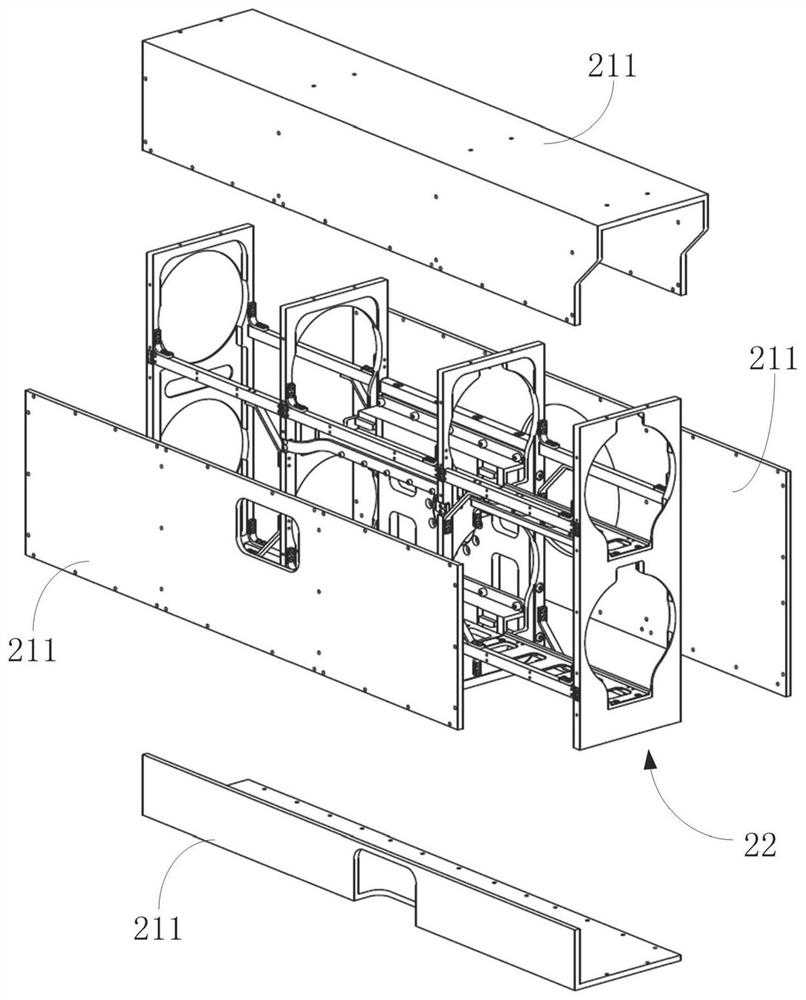
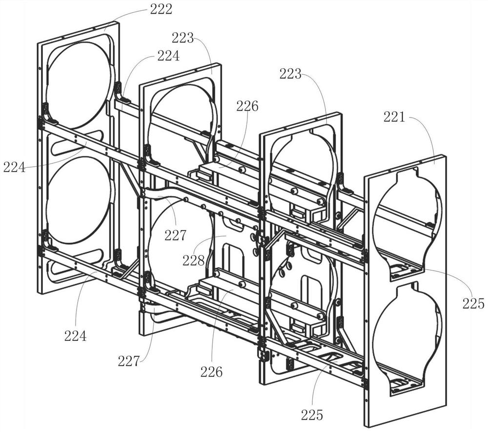
[0033] The embodiment of the present invention provides a protective missile launching box 2, comprising a launching stand 22, which is provided with at least one launching tube mounting position; in one of the embodiments, as figure 2 and image 3 , the launcher 22 adopts a frame structure, including a front panel 221, a rear panel 222, and a plurality of beams 224, and the two ends of each beam 224 are respectively connected with the front panel 221 and the rear panel 222, and the frame structure can better withstand The weight of the missile can ensure sufficient structural stability and a reliable limit effect on the launching tube 1 during the launching process of the missile, so as to reduce unnecessary shaking during the launching process of the missile. Generally, the spacing between the front panel 221 and the rear panel 222 is adapted to the length of the launch tube 1, for example, the spacing is the same as the length of the launch tube 1 or slightly shorter than ...
Embodiment 2
[0053] Such as Figure 8 and Figure 9 , the embodiment of the present invention provides a remote control weapon station, including the protective missile launch box 2 provided in the first embodiment above and a missile launch control unit connected to the installation unit, the missile launch control unit includes a rotary mechanism and a missile Pitch mechanism 42.
[0054] In one of the embodiments, the slewing mechanism includes a slewing platform 41 on which the missile pitching mechanism 42 is arranged, and the above-mentioned launching box 2 is installed on the missile pitching mechanism 42 , that is, the above-mentioned installation unit is connected with the missile pitching mechanism 42 .
[0055] The above-mentioned slewing mechanism can adopt conventional slewing drive equipment, and the missile pitching mechanism 42 can adopt conventional pitching drive equipment, and the specific structure is omitted here.
[0056] In the preferred scheme, such as Figure 8 ...
Embodiment 3
[0059] This embodiment provides an auxiliary bomb feeding device, which can be used in the second embodiment above to feed the machine gun 3 therein.
[0060] Such as Figure 10-Figure 12 , the auxiliary bomb feeding device includes an external energy source picking assembly 31, a sensor 32 and a launch controller 33, and the external energy picking assembly 31 includes a driving mechanism, a transmission mechanism, a one-way clutch 312 and a picking wheel 314, and the sensor The signal output end of 32 is connected with the signal receiving end of launch controller 33, and the signal output end of described launch controller 33 is connected with drive mechanism, and one end of the transmission mechanism is connected with the movable end of drive mechanism, and the other end passes through one-way clutch 312 is connected with the picking wheel 314. In this embodiment, the sensor 32 mainly plays the role of detecting the shooting action of the machine gun and giving the origin...
PUM
 Abstract
Description
Claims
Application Information
 - R&D
- Intellectual Property
- Life Sciences
- Materials
- Tech Scout
- Unparalleled Data Quality
- Higher Quality Content
- 60% Fewer Hallucinations
Browse by: Latest US Patents, China's latest patents, Technical Efficacy Thesaurus, Application Domain, Technology Topic, Popular Technical Reports.
© 2025 PatSnap. All rights reserved.Legal|Privacy policy|Modern Slavery Act Transparency Statement|Sitemap|About US| Contact US: help@patsnap.com


