Self-adaptive mechanical claw based on Van der Waals force and friction force

A friction and self-adaptive technology, applied in the field of robotics, can solve the problems that pure adhesive materials cannot meet the grasping force, large grasping force, and cannot provide

Pending Publication Date: 2022-01-21
HEFEI CSG SMART ROBOT TECH CO LTD
View PDF4 Cites 1 Cited by
  • Summary
  • Abstract
  • Description
  • Claims
  • Application Information

AI Technical Summary

Problems solved by technology

However, conventional mechanical claws often have several problems: First, the current mechanical claws are mostly used to grip objects with regular outer surfaces. For example, Chinese patent CN105563377B discloses a mechanical claw that is only suitable for gripping sheet metal with regular shapes. Object; the second is that the operation of the mechanical claw is completely dependent on the strong mechanical lock based on friction. For example, the Chinese patent CN106142116B discloses a translational variable speed mechanical claw, which completely depends on the clamping force of the two sides of the claw on the object when picking up the object; The third is that pure adhesive materials cannot meet the requirements of applying a large grasping force. For example, Chinese patent CN106564629A discloses a space on-orbit capture device based on bionic gecko dry adhesive materials, and Chinese patent CN110125941B discloses a variable-scale drive bionic dry adhesive. Mechanisms, all rely on the dry adhesion effect based on van der Waals force to adhere to objects, which cannot provide a large grasping force

Method used


Image

  • Self-adaptive mechanical claw based on Van der Waals force and friction force
  • Self-adaptive mechanical claw based on Van der Waals force and friction force
  • Self-adaptive mechanical claw based on Van der Waals force and friction force

Examples


Embodiment Construction

[0025] The following will clearly and completely describe the technical solutions in the embodiments of the present invention with reference to the accompanying drawings in the embodiments of the present invention. Obviously, the described embodiments are only some, not all, embodiments of the present invention. Based on the embodiments of the present invention, all other embodiments obtained by persons of ordinary skill in the art without making creative efforts belong to the protection scope of the present invention.

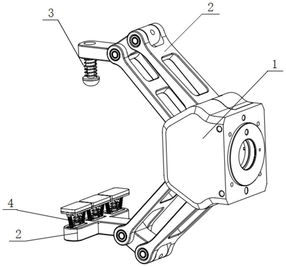
[0026] See figure 1 , an adaptive mechanical gripper based on van der Waals force and friction, including a rotating base 1, two gripper bodies 2 connected to the swivel base 1, and a gripping end connected to one of the gripper bodies 2 The elastic component 3 and three dry adhesive components 4 connected to the clamping end of the other jaw main body 2, the clamping ends of the two clamping jaw main bodies 2 are parallel to each other, and the three dry adhe...


PUM


Abstract

The invention discloses a self-adaptive mechanical claw based on Van der Waals force and friction force. The self-adaptive mechanical claw based on Van der Waals force and friction force comprises a rotating base, two clamping claw main bodies connected to the rotating base, an elastic assembly connected to the clamping end of one clamping claw main body and a plurality of dry adhesion assemblies connected to the clamping end of the other clamping claw main body. According to the invention, a clamping structure of a traditional mechanical claw is changed, one surface of a to-be-clamped piece is extruded through adhesion pads to generate the Van der Waals force, the other surface of the to-be-clamped piece is clamped through elasticity of the elastic assembly and the friction force, the clamping claw main bodies carry out dry adhesion on the to-be-clamped piece through the Van der Waals force, the rotating base drives the to-be-clamped piece to realize rotating operation, and therefore the rotating base does not depend on clamping force of the traditional mechanical clamping claw. Meanwhile, the plurality of dry adhesion assemblies can be subjected to angle adjustment according to the irregular clamping surface of the to-be-clamped piece, so that the adhesion pad of each dry adhesion assembly can be completely adhered to the clamping surface of the to-be-clamped piece, and the purpose of stable clamping is realized.

Description

technical field [0001] The invention relates to the field of robots, in particular to an adaptive mechanical claw based on van der Waals force and frictional force. Background technique [0002] With the gradual development of robot technology, there are more and more fields where robots can be used instead of manual work. In the field of electricity, mechanical claws are more used to replace manual operation of switch buttons. However, conventional mechanical claws often have several problems: First, most of the current mechanical claws are used to grip objects with regular outer surfaces. For example, Chinese patent CN105563377B discloses a mechanical claw that is only suitable for gripping sheet metal with regular shapes. Object; the second is that the operation of the mechanical claw is completely dependent on the strong mechanical lock based on friction. For example, the Chinese patent CN106142116B discloses a translational speed-changing mechanical claw, which complet...

Claims


Application Information

Patent Timeline
Patent Type & Authority Applications(China)
IPC IPC(8): B25J15/08
CPCB25J15/08
Inventor 吴坤汪中原章海兵李林吴哲
Owner HEFEI CSG SMART ROBOT TECH CO LTD
Why Eureka
Try Eureka