
Power supply control device of electric anastomat and electric anastomat

A technology of power control device and stapler, which is applied to circuits, electrical switches, electrical components, etc., can solve the problems of power loss, limited space, and inability to judge the use of battery packs, so as to prevent misoperation and ensure safety.

Active Publication Date: 2022-01-21
SUZHOU FRANKENMAN MEDICAL EQUIP
View PDF12 Cites 2 Cited by
  • Summary
  • Abstract
  • Description
  • Claims
  • Application Information

AI Technical Summary

Problems solved by technology

Considering the limited space and safety issues of electric staplers, there are few built-in power supplies, and external power supplies are likely to cause problems such as loss
However, the built-in battery pack is pre-installed in the inner cavity of the electric stapler, and the user cannot judge the use of the battery pack. Generally, after pressing the switch on the handle several times, it is impossible to judge whether the battery pack has been used in the next operation.

Method used


Image

  • Power supply control device of electric anastomat and electric anastomat
  • Power supply control device of electric anastomat and electric anastomat
  • Power supply control device of electric anastomat and electric anastomat

Examples


Embodiment

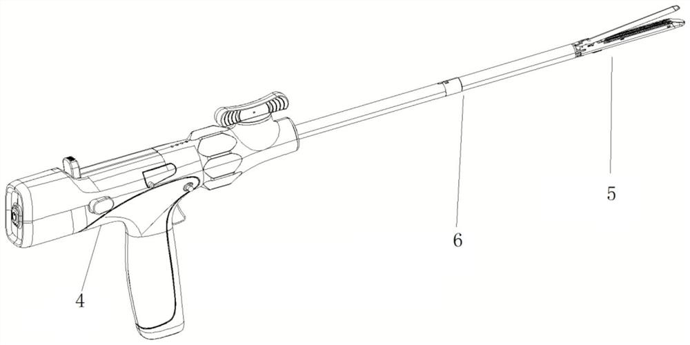
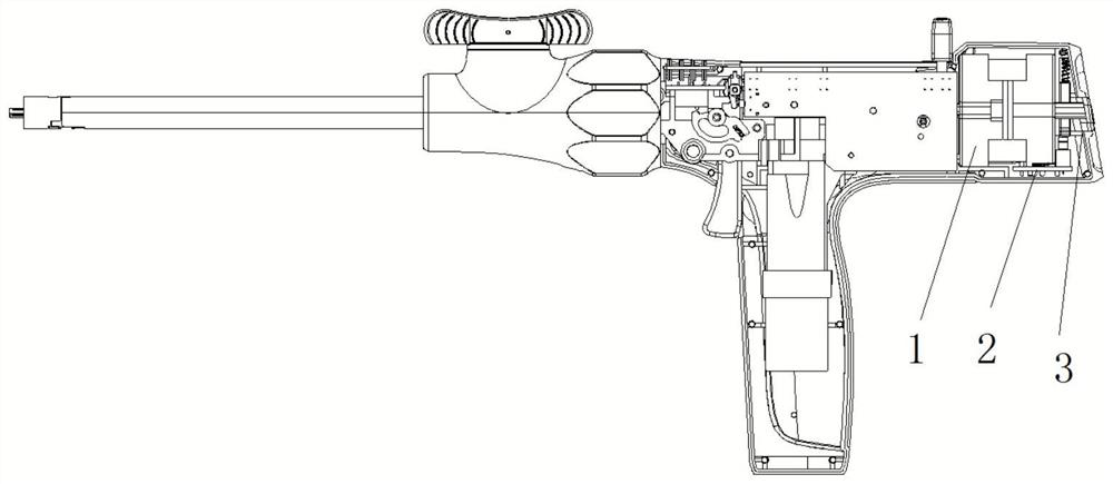
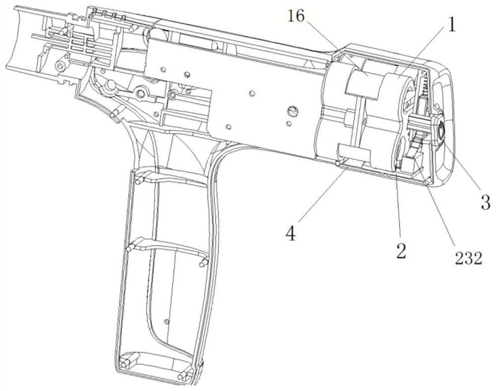
[0041] Such as Figure 1-14 As shown, in this embodiment, an electric stapler power control device and an electric stapler are provided. The electric stapler in this embodiment includes a handle housing 4, an actuator assembly 5, a driving motor, a connecting tube 6 and a driving assembly. Among them, the handle housing 4 is used to accommodate the drive motor and part of the drive assembly. The drive assembly passes through the connecting pipe and is connected to the actuator assembly 5. The actuator assembly 5 includes a clamp, a cutter, and an actuator push rod. After the clamping part is closed, the cutting knife is pushed to cut the tissue. During this process, the staples are pushed out along with the advancement of the cutting knife, thereby realizing the anastomosis process. In this embodiment, a built-in stapler power supply is also provided in the handle housing 4, and the power supply is used to supply power to the driving motor to realize the electric driving proce...


PUM


Abstract

The invention discloses a power supply control device of an electric anastomat and the electric anastomat. The power supply control device comprises a control switch assembly, a power supply assembly and a circuit connecting base, wherein the power supply assembly and the circuit connecting base are located in a handle shell containing cavity; the power supply assembly is electrically connected with the circuit connecting base, and the circuit connecting base is provided with a driving wire used for being electrically connected with an anastomat driving source and a pressing control part used for controlling a circuit to be connected and disconnected; the control switch assembly comprises a pressing piece and a triggering piece, when the pressing piece is located at the first position, the triggering piece is limited to move towards the triggering position, and when the pressing piece is located at the second position, the triggering piece can move from the initial position to the triggering position so as to drive the pressing control part to a circuit connection position; and when the triggering piece is located at the triggering position, the pressing piece is limited to move towards the first position. Through blocking cooperation of the pressing piece and the triggering piece, after a power source is used once, the control switch assembly cannot return and reset, and the risk caused by secondary utilization of the power source of the electric anastomat is prevented.

Description

technical field [0001] The invention relates to a medical device, in particular to an electric stapler power control device and an electric stapler. Background technique [0002] Endoluminal staplers may generally include two elongated jaw members for grasping or clamping tissue, respectively. In some surgical staplers, one of the jaw members has a staple magazine loaded with a plurality of staples arranged in at least two horizontal rows, and the other jaw member has an anvil, which When the staple cartridge is pushed out, the anvil defines a surface for forming the staple legs. During the stapling operation, the staples are sequentially ejected from the staple cartridge by pushing the blade, and the blade can travel between rows of staples to longitudinally cut the stapled tissues between the rows of staples. According to different power transmission methods, staplers can be divided into manual and electric. Different from the mechanical control of the traditional manua...

Claims


Application Information

Patent Timeline
Patent Type & Authority Applications(China)
IPC IPC(8): A61B17/072H01H13/14H01H13/20
CPCA61B17/07207H01H13/14H01H13/20A61B2017/00389A61B2017/00017A61B2017/0046A61B2560/0214Y02E60/10
Inventor 毛训根沈伟庆陆春明
Owner SUZHOU FRANKENMAN MEDICAL EQUIP
Learn More