Ethernet power supply device and system

A power supply device, Ethernet technology, applied in data switching current source, data exchange details, advanced technology and other directions, can solve problems such as short life and poor contact reliability

Pending Publication Date: 2022-01-14
XIAMEN YEALINK NETWORK TECH
View PDF0 Cites 0 Cited by
  • Summary
  • Abstract
  • Description
  • Claims
  • Application Information

AI Technical Summary

Problems solved by technology

[0004] However, the switching scheme mentioned in the prior art belongs to mechanical switch switching, which has the problems of poor contact reliability and short service life

Method used


Image

  • Ethernet power supply device and system
  • Ethernet power supply device and system
  • Ethernet power supply device and system

Examples


Embodiment Construction

[0049] In order to make the purpose, technical solutions and advantages of the embodiments of the present application clearer, the technical solutions in the embodiments of the present application will be clearly and completely described below in conjunction with the drawings in the embodiments of the present application. It should be understood that the appended The figures are only for the purpose of illustration and description, and are not used to limit the protection scope of the present application. Additionally, it should be understood that the schematic drawings are not drawn to scale. The flowcharts used in this application illustrate operations implemented in accordance with some embodiments of the application. It should be understood that the operations of the flowcharts may be performed out of order, and steps that have no logical context may be performed in reverse order or concurrently. In addition, those skilled in the art may add one or more other operations t...


PUM


Abstract

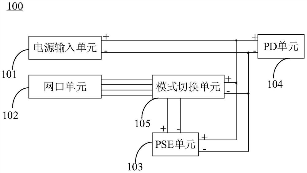
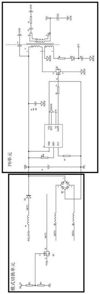
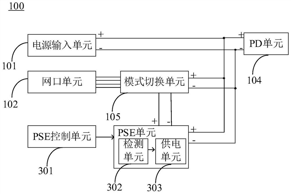
The invention provides an Ethernet power supply device and system, and relates to the technical field of Ethernet power supply. The device comprises a power supply input unit, a network port unit, a PSE unit, a PD unit and a mode switching unit, wherein the power supply input unit is connected with the PSE unit, the PD unit and the mode switching unit; the network port unit is connected with the mode switching unit, and the mode switching unit is used for outputting a mode switching control signal under triggering of a power supply signal provided by the power supply input unit and outputting power supply voltage output by the PSE unit to external power receiving equipment connected with the network port unit; and the mode switching unit is also used for receiving power supply voltage output by external power supply equipment through the network port unit when the power supply signal provided by the power supply input unit is not received, and providing the power supply voltage output by the external power supply equipment to each unit in the Ethernet power supply device through the PD unit. According to the invention, switching between a PSE mode and a PD mode of the Ethernet power supply device is realized, and the purpose of bidirectional power supply through a single network port is achieved.

Description

technical field [0001] The present invention relates to the technical field of Ethernet power supply, in particular, to an Ethernet power supply device and system. Background technique [0002] Power Over Ethernet (POE for short) refers to the transmission of data for some terminals based on the Interworking Protocol (IP) without any changes to the existing Ethernet Cat. At the same time as the signal, it can also provide DC power supply technology for such IP terminal equipment. [0003] At present, in the POE power supply IEEE802.3af specification, the power supply equipment (Power Sourcing Equipment, PSE for short) mode and the powered device (Powered Device, PD for short) mode in the POE power supply system usually use a network port to realize their own power supply and receiving. Electrical function; however, only a single network port can be placed on some POE products with limited interface space. This network port must support both PD and PSE functions, and when th...

Claims


Application Information

Patent Timeline
IPC IPC(8): H04L12/10H04L12/12
CPCH04L12/10H04L12/12Y02D30/50
Inventor 叶江彬
Owner XIAMEN YEALINK NETWORK TECH
Why Eureka
Try Eureka