Inserting row for industrial furnaces

A technology for industrial furnaces and sockets, applied in furnaces, heat treatment furnaces, manufacturing tools, etc., can solve the problems that conventional sockets cannot meet, and achieve the effects of simple structure, convenient operation, light and flexible structure

Pending Publication Date: 2019-08-09
HENAN TIANLI THERMOTECHNICAL EQUIP CO LTD
View PDF0 Cites 0 Cited by
  • Summary
  • Abstract
  • Description
  • Claims
  • Application Information

AI Technical Summary

Problems solved by technology

[0002] The trolley of the new industrial furnace has three stations. The trolley loads the workpiece at the first station, the second station enters the furnace to heat the workpiece, and the third station unloads the workpiece. The three stations are not in the furnace shell. On the same side; due to space constraints, the customer requires that the workpiece be loaded on the left side of the furnace shell and heated in the furnace. The qualified background car drives to the right side of the furnace shell and pours the workpiece into the quenching pool on the right; The trolley needs to be connected to the power supply to be heated; the existing conventional plug-in strips cannot meet the requirements of the furnace

Method used


Image

  • Inserting row for industrial furnaces

Examples


Embodiment Construction

[0008] Embodiments are described in detail in conjunction with the accompanying drawings,

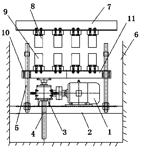
[0009] An insertion row used on an industrial furnace, which includes a fixed insertion row, a fixed insertion row 8 is provided at the bottom of the trolley 7, a pit 6 is preset at the center of the track in the furnace body, and a fixed bottom plate is arranged in the pit 2. One side of the fixed bottom plate is provided with a rotating motor 1, the output shaft of the motor drives the screw lifter 3, the upper part of the ejection shaft 4 of the screw lifter is fixedly connected with the movable frame 11, and the movable rack 9 is arranged above the movable frame, and the movable frame Both ends of the guide sleeve 10 are provided, the guide sleeve is set on the guide rod 5, and the guide rod is fixed on the fixed base plate;

[0010] The present invention can also increase the trolley positioning device to facilitate better positioning of the trolley. The trolley positioning device ...


PUM


Abstract

The invention provides an inserting row for industrial furnaces. The inserting row for the industrial furnaces comprises a fixed inserting row, wherein the fixed inserting row body is arranged at thebottom of a trolley; a pit is pre-arranged at the central position of a track in a furnace body; a fixed bottom plate is arranged in the pit; a rotating motor is arranged on one side of the fixed bottom plate; an output shaft of the motor drives a lead screw elevator; an ejection shaft of the lead screw elevator is fixedly connected with a movable frame; a movable inserting row body is arranged above the movable frame; guide sleeves are arranged at both ends of the movable frame; the guide sleeves sleeve on guide rods; and the guide rods are fixed to the fixed bottom plate. The inserting row for the industrial furnaces is light and flexible in structure, simple in structure and convenient to operate and maintain, and realizes the purpose of supplying power to the trolley in a high-temperature environment.

Description

technical field [0001] The invention relates to an industrial furnace, in particular to an insertion row suitable for the industrial furnace. Background technique [0002] The trolley of the new industrial furnace has three stations. The trolley loads the workpiece at the first station, the second station enters the furnace to heat the workpiece, and the third station unloads the workpiece. The three stations are not in the furnace shell. On the same side; due to space constraints, the customer requires that the workpiece be loaded on the left side of the furnace shell and heated in the furnace. The qualified background car drives to the right side of the furnace shell and pours the workpiece into the quenching pool on the right; The trolley needs to be connected to the power supply to be heated; the existing conventional plug-in strips cannot meet the requirements of the furnace. Contents of the invention [0003] The purpose of the present invention is to design a plug-...

Claims


Application Information

Patent Timeline
Patent Type & Authority Applications(China)
IPC IPC(8): C21D1/63C21D9/00
CPCC21D1/63C21D9/00
Inventor 李振欣杨利伟李明科
Owner HENAN TIANLI THERMOTECHNICAL EQUIP CO LTD
Why Eureka
Try Eureka