
Radio frequency spectrum sensor

A technology of radio frequency spectrum and sensors, which is applied to the components of electrical measuring instruments, instruments, and measuring electronics. It can solve the problems of time-consuming, labor-intensive installation, and low efficiency, and achieve convenient transfer, improve installation efficiency, and prevent shrinkage under pressure. Effect

Pending Publication Date: 2022-01-14
成都老鹰信息技术有限公司
View PDF17 Cites 0 Cited by
  • Summary
  • Abstract
  • Description
  • Claims
  • Application Information

AI Technical Summary

Problems solved by technology

[0004] However, this solution still has some shortcomings. When using the radio spectrum sensor, the radio spectrum sensor needs to be installed on a bracket or other facilities before it can be used. The installation is time-consuming and laborious, and the efficiency is low.

Method used


Image

  • Radio frequency spectrum sensor
  • Radio frequency spectrum sensor

Examples


Embodiment 1

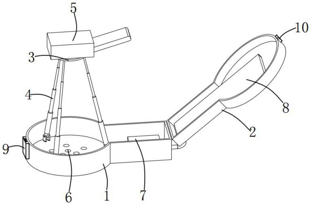
[0024] Such as figure 1 As shown, the radio frequency spectrum sensor provided by the present invention includes: a box body 1, an upper cover 2 is rotatably installed on the box body 1, and three telescopic rods 4 are rotatably installed in the box body 1, and three telescopic rods 4 are installed on the box body 1. The top of the rod 4 is rotatably mounted with a fixed plate 3 on which a sensor body 5 is mounted, and a handle is mounted on one side of the box body 1 .

[0025] In this embodiment, by stretching or shrinking the telescopic rod 4, the sensor body 5 installed on the fixed plate 3 can be lifted up and down, so that the sensor body 5 can be quickly raised to the use height when in use, and the installation efficiency can be improved. When not in use, the sensor body 5 is stored in the box body 1 and the upper cover 2 to protect the sensor body 5, and at the same time, the handle is lifted to facilitate transportation.

Embodiment 2

[0027] Such as figure 1 As shown, the box body 1 is provided with a plurality of ventilation holes 6 .

[0028] In this embodiment, during storage, the air holes 6 play a role of ventilation to reduce the humidity inside the box body 1 , and during use, the air holes 6 play a role of drainage in rainy weather.

Embodiment 3

[0030] Such as figure 1 As shown, a first anti-vibration pad 7 is installed in the box body 1 , and a second anti-vibration pad 8 is installed in the upper cover 2 .

[0031] In this embodiment, the first anti-vibration pad 7 and the second anti-vibration pad 8 are adapted to the shape of the sensor body 5, and when the sensor body 5 is stored, the first anti-vibration pad 7 and the second anti-vibration pad 8 hold the sensor body 5 The top and bottom are clamped, which not only plays a fixed role but also plays a certain role in shock absorption.


PUM


Abstract

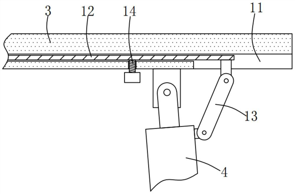
The invention discloses a radio frequency spectrum sensor. The radio frequency spectrum sensor comprises a box body, an upper cover is installed on the box body, three telescopic rods are installed in the box body, a fixing plate is installed at the tops of the three telescopic rods, and a sensor body is installed on the fixing plate. According to the radio frequency spectrum sensor provided by the invention, the sensor body mounted on the fixing plate can be lifted by stretching or retracting the telescopic rods, so that the sensor body can be quickly lifted to a use elevation during use, the mounting efficiency is improved, and meanwhile, the sensor body is stored in the box body and the upper cover when not in use, the sensor body is protected, meanwhile, transferring is convenient, the angle fixing effect on the telescopic rod is achieved through a guide rod, a connecting rod and a limiting screw, and the telescopic rod is prevented from being pressed to retract in the using process.

Description

technical field [0001] The invention relates to the technical field of radio monitoring, in particular to a radio frequency spectrum sensor. Background technique [0002] Using advanced technical means and certain equipment to measure radio transmission frequency, power, transmission bandwidth, etc., to monitor analog FM, AM and other signals, to find direction, locate, and approach illegal radio stations and interference sources. Radio monitoring refers to the activities of detecting, searching, and intercepting radio signals in the radio management area, and analyzing, identifying, monitoring and obtaining technical information such as technical parameters, working characteristics and radiation positions of the radio signals. It is an effective implementation It is an important basis for radio management and also an important branch of radio spectrum management. In the current mainstream radio monitoring technology, the base station monitoring is more commonly used. Gener...

Claims


Application Information

Patent Timeline
Patent Type & Authority Applications(China)
IPC IPC(8): G01R1/04G01R1/02G01R23/16H04B17/00H05K5/02H05K7/00
CPCG01R1/0408G01R1/04G01R1/02G01R23/16H04B17/00H05K5/02H05K5/0213H05K7/00
Inventor 杨解清
Owner 成都老鹰信息技术有限公司
Learn More