A long-span box beam dynamic bending ultimate strength test device

A technology of dynamic bending and ultimate strength, applied in the direction of applying stable bending force to test the strength of materials, measuring devices, strength characteristics, etc., can solve the problems of model impact damage, long span of structures, box girder prone to bounce, etc. Achieve the effects of preventing the secondary impact of the falling hammer, flexibly changing and adjusting, and speeding up the experiment

Active Publication Date: 2022-08-02
SHANGHAI JIAOTONG UNIV
View PDF10 Cites 0 Cited by
  • Summary
  • Abstract
  • Description
  • Claims
  • Application Information

AI Technical Summary

Problems solved by technology

[0004] The existing impact testing machine has the following problems: ships and marine engineering structures have long spans, and the model scale is still large after considering a certain scale ratio, which exceeds the allowable scale range of the existing impact testing machine; during the test, the box girder After the mid-span is subjected to the impact load, the two ends of the box girder are prone to bounce, which may cause the box girder to deviate from the predetermined position, and it is difficult to appear the expected dynamic failure mode; the existing impact testing machine can only provide the drop hammer impact in the form of concentrated force It is difficult to realize the pure bending loading of the box girder; after the drop weight impacts the test model, it will bounce up, causing secondary or multiple impact damage to the model, which affects the judgment and analysis of the failure mode of the test model. Therefore, a long-span Box girder dynamic bending ultimate strength test device

Method used


Image

  • A long-span box beam dynamic bending ultimate strength test device
  • A long-span box beam dynamic bending ultimate strength test device
  • A long-span box beam dynamic bending ultimate strength test device

Examples


Embodiment Construction

[0036] In order to more clearly understand the above objects, features and advantages of the present invention, the present invention will be further described in detail below with reference to the accompanying drawings and specific embodiments. It should be noted that the embodiments of the present application and the features in the embodiments may be combined with each other under the condition of no conflict.

[0037]Many specific details are set forth in the following description to facilitate a full understanding of the present invention. However, the present invention can also be implemented in other ways different from those described herein. Therefore, the protection scope of the present invention is not limited by the specific details disclosed below. Example limitations.

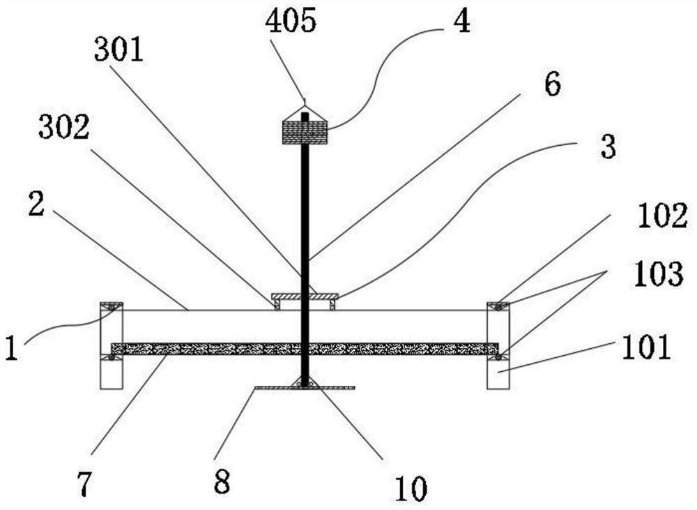
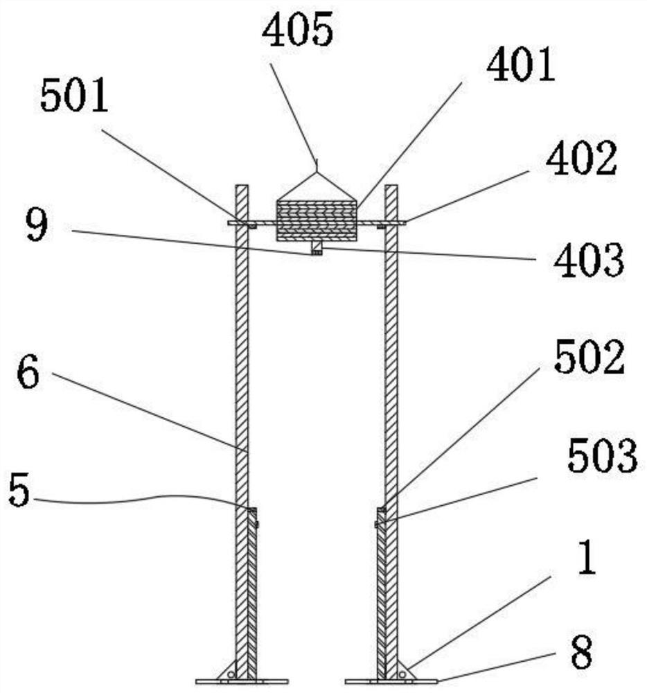
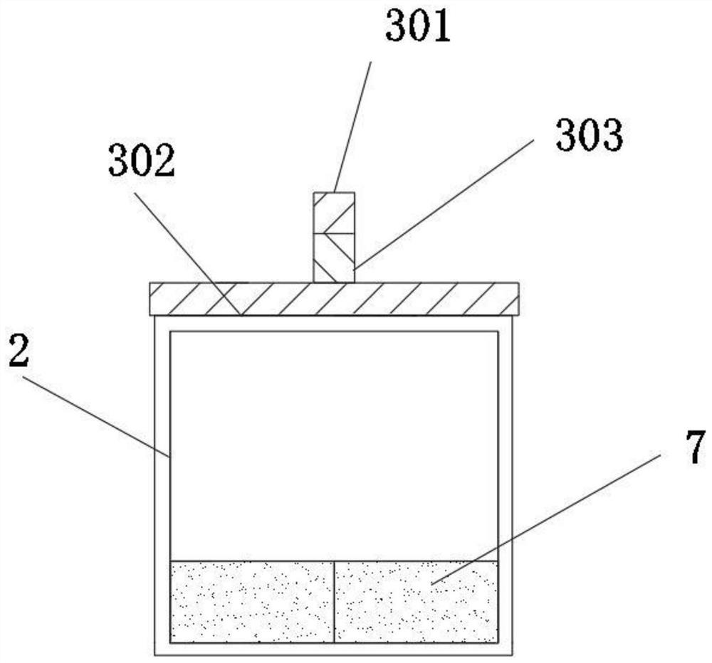
[0038] see Figure 1-5 , the embodiment of the first aspect of the present invention provides a long-span box beam dynamic bending ultimate strength test device, including: a fixed part 1, the fi...


PUM


Abstract

The invention discloses a dynamic bending ultimate strength test device of a long-span box beam, which realizes the dynamic pure bending load loading of a box beam test model through an assembled drop weight and a distribution beam, and changes the dynamic load amplitude by adjusting the weight and height of the drop weight. The natural vibration frequency of the box beam test model is changed by adjusting the single weight and number of the counterweight part, the secondary impact of the drop weight is prevented by the joint control of the electromagnet and the laser sensor, and the two fixed parts are clamped and fixed and slidingly contacted. It can be plugged and fixed, which facilitates the fixing of box beam test models of different lengths. At the same time, the fixed part and the guide frame of the device adopt a separate design, which can be flexibly changed and adjusted, which is convenient for operation and accelerates the test speed. The end is clamped and fixed to prevent the box beam test model from bouncing after being impacted.

Description

technical field [0001] The invention relates to the technical field of engineering experimental equipment, in particular to a dynamic bending ultimate strength test device of a long-span box beam. Background technique [0002] In the structural test, the impact test of the structure is carried out using the drop weight impact test device, and the structural failure and ultimate strength under the impact load are analyzed, which is of great significance for revealing the dynamic failure mechanism of the structure. [0003] The principle of the drop weight impact test is to adjust the weight of the drop weight and lift it to a predetermined height, release the drop weight to fall freely, reach a certain impact speed at the moment of contact with the test model, convert the gravitational potential energy into kinetic energy, and apply a vertical downward force to the test model. dynamic load. [0004] The existing impact testing machine has the following problems: the span of ...

Claims


Application Information

Patent Timeline
Patent Type & Authority Patents(China)
IPC IPC(8): G01N3/02G01N3/303G01N3/20
CPCG01N3/02G01N3/303G01N3/20
Inventor 师桂杰蔡诗剑王福花王德禹崔进举蔡忠华陈涛熊宇飞刘亚冲
Owner SHANGHAI JIAOTONG UNIV
Why Eureka
Try Eureka