
Reciprocating type underwater power conversion device

A power conversion, reciprocating technology, applied in the directions of hydroelectric power generation, engine function, engine components, etc., can solve the problems such as the need to improve the economic benefits of use, high construction and maintenance costs, low underwater energy conversion rate, etc., and achieve breakthrough in manufacturing costs. Expensive, simple and compact structure, stable effect of continuous motion

Pending Publication Date: 2022-01-14
赵辉
View PDF0 Cites 0 Cited by
  • Summary
  • Abstract
  • Description
  • Claims
  • Application Information

AI Technical Summary

Problems solved by technology

[0003] At present, the movement of water bodies contains huge energy, which is not fully exploited by people, and most of the energy conversion devices in water bodies are relatively complicated. The energy of the ebb tide is converted into mechanical energy, and then the process of converting mechanical energy into electrical energy has a complex structure, many components, high construction and maintenance costs, low underwater energy conversion rate, and the use of economic benefits needs to be improved

Method used


Image

  • Reciprocating type underwater power conversion device

Examples


Embodiment Construction

[0014] The structure and working principle of a reciprocating underwater power conversion device provided by the present invention will be further described in detail below in conjunction with the accompanying drawings.

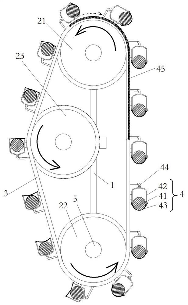
[0015] see figure 1 , is a structural schematic diagram of a reciprocating underwater power conversion device provided by the present invention. The structure constituting the reciprocating underwater power conversion device includes a frame 1 placed in a flowing water body or a still water body, an upper transmission shaft 21 and a lower transmission shaft 22 arranged in the frame 1, and the upper transmission shaft 21 and the lower transmission shaft 22. The synchronous linkage is realized by the closed chain 3 surrounding the two. Several vertically arranged energy conversion units 4 are arranged on the closed chain 3. The energy conversion unit 4 includes a piston cylinder 42 with a piston body 41 inside. One end of the piston cylinder 42 is open and defo...


PUM


Abstract

The invention belongs to the technical field of fluid mechanics, and particularly relates to a reciprocating type underwater power conversion device. The reciprocating type underwater power conversion device structurally comprises a rack arranged in a flowing water body or a static water body, an upper transmission shaft and a lower transmission shaft, wherein the upper transmission shaft and the lower transmission shaft are arranged in the rack and are synchronously linked through a closed chain surrounding the upper transmission shaft and the lower transmission shaft. The chain is provided with a plurality of vertically-arranged energy conversion units. Each energy conversion unit comprises a piston barrel internally provided with a piston body, wherein an opening in one end of the piston barrel communicates with a deformation bag, the other end of the piston barrel is a closed face provided with air holes, the air holes in the piston barrels located on the two sides of the closed chain communicate with each other through a pipeline, and pre-pressing gas in the piston barrels flows in a space between the piston barrels on the two sides of the closed chain in a reciprocating manner. According to the reciprocating type underwater power conversion device, sufficient conversion of underwater energy is achieved, power can be rapidly and continuously output, and the reciprocating type underwater power conversion device has the characteristics of being simple and compact in structure and convenient and fast to use.

Description

technical field [0001] The invention belongs to the technical field of fluid mechanics, and in particular relates to a reciprocating underwater power conversion device. Background technique [0002] Fluid is the general term for gas and liquid. Fluid can be encountered anytime and anywhere in people's life and production activities, so fluid mechanics is closely related to human daily life and production. For example, the atmosphere surrounds the entire earth, and 70% of the earth's surface is water. The movement of the atmosphere, sea water (including waves, tides, mesoscale vortices, circulation, etc.) and even the flow of molten magma deep in the earth are all hydrodynamic research content. [0003] At present, the movement of water bodies contains huge energy, which is not fully exploited by people, and most of the energy conversion devices in water bodies are relatively complicated. The energy of the ebb tide is converted into mechanical energy, and then the process o...

Claims


Application Information

Patent Timeline
Patent Type & Authority Applications(China)
IPC IPC(8): F03B13/00F03B13/26F03B11/00
CPCF03B13/00F03B13/26F03B11/00F05B2260/4022Y02E10/20Y02E10/30
Inventor 赵辉
Owner 赵辉
Learn More