Pedal bicycle

A bicycle and frame technology, applied in the field of pedal bicycles, can solve the problems of coaxiality, damage to the transmission system, waste of favorable conditions for the driving force arm, etc., and achieve the effects of long force arm, compact structure, and no free travel on the transmission.

Pending Publication Date: 2022-01-14
西安双驱自正智能科技有限公司
View PDF1 Cites 0 Cited by
  • Summary
  • Abstract
  • Description
  • Claims
  • Application Information

AI Technical Summary

Problems solved by technology

Although the length of the force arm of this reciprocating mechanism is not limited by the distance between the rotation axis and the ground, but by the telescopic distance of the legs, its actual force arm is the length of the driving force arm minus the resistance arm. The shorter the moment arm, the harder it is
[0005] There is also a bicycle that enters the market now, produced by Chongqing Qikebi Bicycle Co., Ltd., called random ride, patent CN201210036555.2. The one-way bearing in the one-way overrunning clutch is used in the first-level position, and the advantages of the one-way bearing can be adjusted arbitrarily. The resistance arm is the radius of the one-way bearing, which is much smaller than the length of the power arm, but it is different from the traditional bicycle. The riding style is the same. Its power arm still turns a full circle like the crank of a traditional bicycle. The length is naturally limited by the distance between the axis and the ground. In order to allow the human leg to apply force at any angle, there is no force arm limiter. The disadvantage is that when the stretching amount of the legs is greater than the length of the crank, the actual length of the arm will be shorter than the length of the crank; and the arm can rotate a full circle and cannot touch the ground. There are structural shortcomings: the use of one-way bearings is abandoned Finally, the length of the pedal can be set to be much greater than the distance from the pedal axis to the ground to increase the favorable conditions for the power arm and the actual driving force arm; The bridge gear makes the left and right driving arms associated, and its disadvantage is that it cannot realize independent and simultaneous double drive of the left and right driving arms
Although it can be stepped on both positive and negative, or through the initial setting of the left and right crank angles less than 180 degrees, even if the same direction is alternately stepped on, the output curve of the driving force can be converted from the trough of the traditional bicycle to the peak, but due to this initial setting "Hard" association, in the actual riding process, the rider cannot independently and more effectively choose the peak section of the driving force output; in addition, due to the blocking of the bridge gear added between the left and right cranks, the installation position of the entire device It is limited, for example, it is impossible to realize that the center shaft, that is, the driving chain disc shaft, cannot be coaxial with the rear wheel, that is, the driving wheel, so that the extremely simplified design of the whole vehicle cannot be realized, and especially the longer favorable conditions for realizing the driving arm are wasted; in addition It does not have a neutral clutch device, and it is easy to cause damage to the components of the transmission system when the reverse wheel force is too large

Method used


Image

  • Pedal bicycle
  • Pedal bicycle
  • Pedal bicycle

Examples


specific Embodiment approach

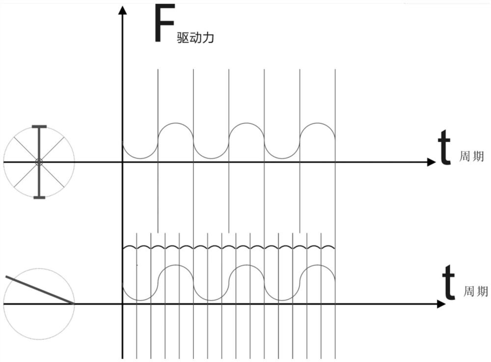
[0048] figure 1 , which is the design efficiency index that guides our design target ideal state, and the output curve of the product power produced by the final design is figure 1 The thick wavy lines with a short period in the lower half have just reached the ultimate beneficial effect of the present invention.

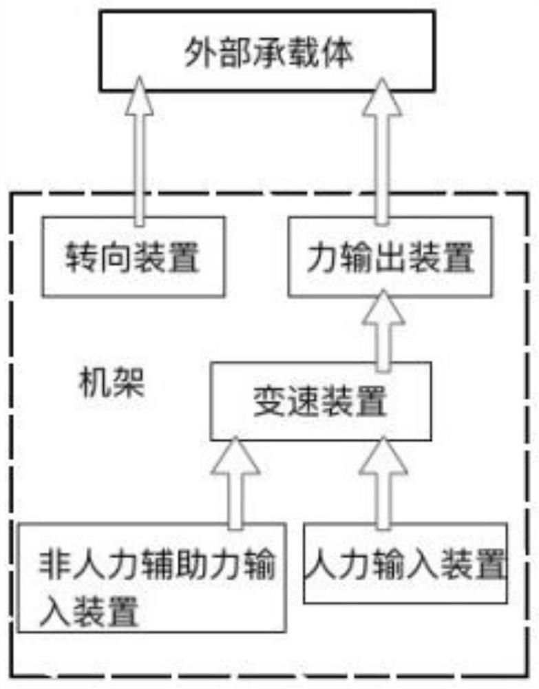
[0049] figure 2 , is exactly the logic diagram between each device of the present invention, and the arrow represents the direction of force transmission, and the force output device is the rear wheel that is connected with the transmission.

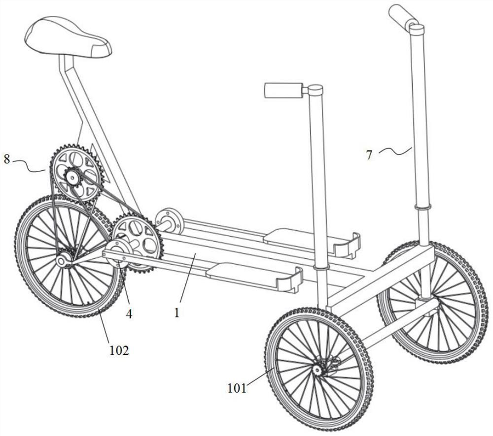
[0050] It includes a vehicle frame 1, and a manual variable speed drive device installed on the vehicle frame, a steering device 7, a front wheel 101, and a rear wheel 102;

[0051] The manpower variable speed driving device includes: frame, force application handle 2, main drive shaft 3, one-way overrunning clutch 4, reset device 6, speed change gear set 8, one end of force application handle is fixed with the input end of...


PUM


Abstract

The invention provides a pedal bicycle which is characterized by comprising a frame, and a manual variable speed driving device, a steering device, a front wheel and a rear wheel which are mounted on the frame, the manual variable speed driving device comprises a rack, a force application handle, a main power shaft, a one-way overrunning clutch, a reset device and a variable speed gear set, one end of the force application handle is fixed to the input end of the one-way overrunning clutch, and the output end of the one-way overrunning clutch is fixed to the main power shaft; the force application handle rotates around the main power shaft in a reciprocating mode to sweep a sector face to move and do work, the driving force arm corresponding to the force application handle directly drives the input end of the one-way overrunning clutch to rotate forwards and backwards, and therefore the output end of the one-way overrunning clutch is intermittently driven to rotate in a one-way mode. The variable speed gear set is an angular speed increasing gear set and comprises an input end gear, a middle change gear set and a terminal gear which are in transmission connection in sequence. The power output efficiency is high, the structure is compact, no idle stroke exists in transmission, and safety and comfort are achieved.

Description

technical field [0001] The invention relates to the field of transportation tools, in particular to a pedal bicycle. Background technique [0002] The power conversion transmission mechanism of a traditional pedal bicycle includes a center shaft assembly, a crank assembly, a rear wheel shaft assembly, and a driving chain plate, a chain, and a driven sprocket assembly; its power comes from the continuous circular motion of human legs, Drive the left and right cranks and the driving chain plate to rotate continuously 360°, and the power is transmitted from the driving chain plate to the driven sprocket and finally to the rear wheel shaft through the chain, so that the bicycle can move forward. [0003] Traditional pedal bicycles have poor driving performance and laborious riding, which is mainly related to the driving mode. Limited by the movement distance of the human legs and the minimum ground clearance of the pedals, the design length of the crank can only be limited to a ...

Claims


Application Information

Patent Timeline
IPC IPC(8): B62M1/28B62M1/30B62M9/04B62M11/04B62K5/05
CPCB62M1/28B62M1/30B62M9/04B62M11/04B62K5/05
Inventor 郑健黑京京刘晓燕李小超
Owner 西安双驱自正智能科技有限公司
Why Eureka
Try Eureka