Polyurethane foaming machine for artificial limb production

A foaming machine and polyurethane technology, which is applied in the field of polyurethane foaming machines for prosthetic limb production, can solve the problems of prolonged processing, delayed production efficiency, poor stirring effect, etc., and achieves the effects of quick installation, improved production efficiency and production quality.

Pending Publication Date: 2022-01-14
朱利群
View PDF0 Cites 0 Cited by
  • Summary
  • Abstract
  • Description
  • Claims
  • Application Information

AI Technical Summary

Problems solved by technology

Its applicable objects are amputees due to diseases, traffic accidents, industrial accidents, sports trauma and other reasons. Polyurethane foaming machines are used in the surface processing of prostheses, and polyurethane foaming machines are special equipment for pouring and foaming polyurethane foam plastics. , mainly the raw liquids of components A and B are accurately proportioned and stirred at a high speed, and two high-precision metering pumps transport the two components of A and B to the mixing head respectively, and after high-speed and strong stirring, the The material liquid is evenly sprayed out to form the desired product. As long as the performance index of the raw material of the polyurethane component meets the formula requirements, uniform and qualified foam products can be produced through this equipment, so it is widely used, but the existing There are also some problems in the polyurethane foam machine that need to be solved, mainly because the raw material stirring device of the polyurethane foam machine has a poor stirring effect when foaming, and it often takes more time to stir the raw materials, resulting in prolonged processing and easy delays in production efficiency

Method used


Image

  • Polyurethane foaming machine for artificial limb production
  • Polyurethane foaming machine for artificial limb production
  • Polyurethane foaming machine for artificial limb production

Examples


Embodiment Construction

[0022] The following will clearly and completely describe the technical solutions in the embodiments of the present invention with reference to the accompanying drawings in the embodiments of the present invention. Obviously, the described embodiments are only some, not all, embodiments of the present invention. Based on the embodiments of the present invention, all other embodiments obtained by persons of ordinary skill in the art without making creative efforts belong to the protection scope of the present invention.

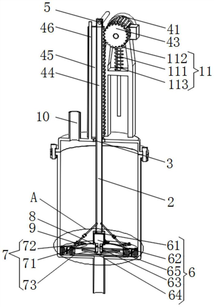
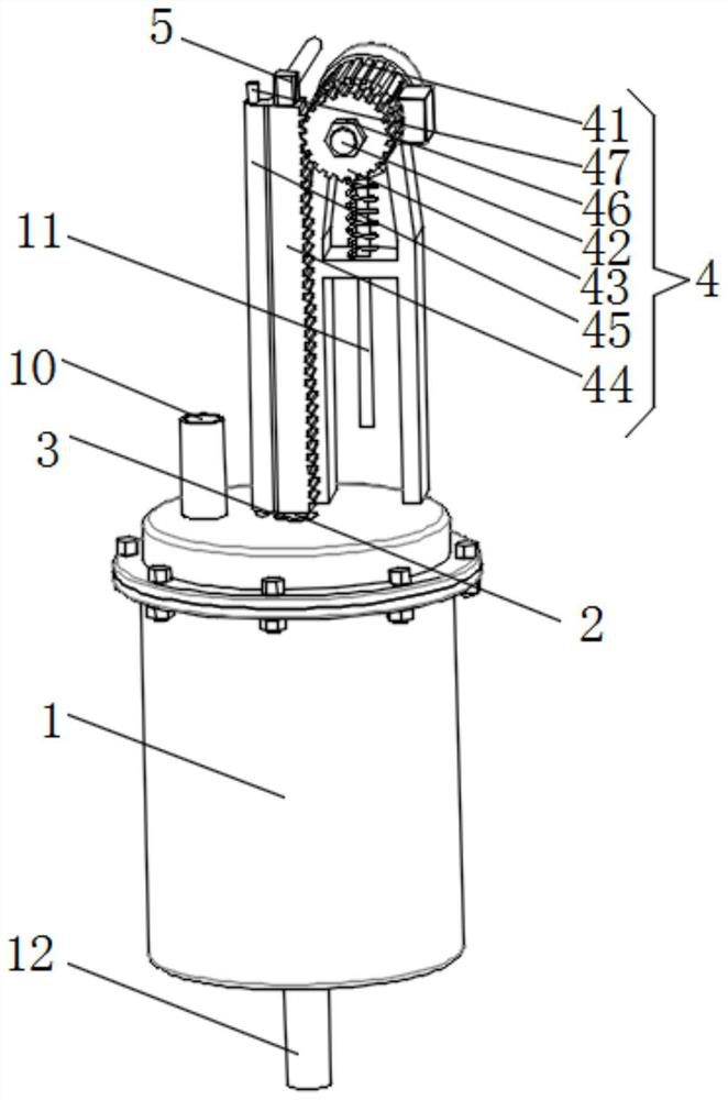
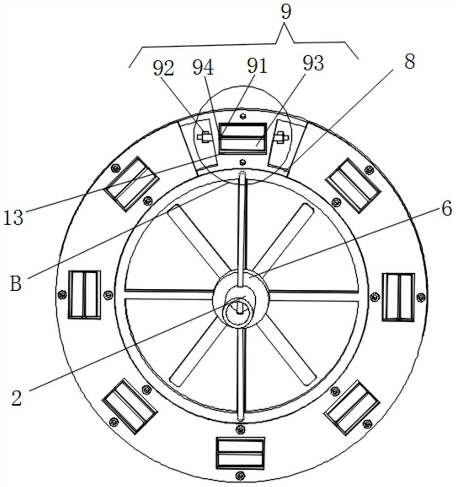
[0023] see figure 1 , figure 2 , Figure 5 , a polyurethane foaming machine for prosthesis production, comprising a foaming machine raw material tank 1, the inner side of the middle part of the foaming machine raw material tank 1 is movably connected with a transitional hollow rod 2, and the middle part of the transitional hollow rod 2 is connected to the foaming machine raw material tank 1 The first shaft sealing ring 3 is installed at the connection insid...


PUM


Abstract

The invention relates to the technical field of foaming machines, and discloses a polyurethane foaming machine for artificial limb production. The polyurethane foaming machine comprises a foaming machine raw material tank, the inner side of the middle of the foaming machine raw material tank is movably sleeved with a transition hollow rod, and a first shaft sealing ring is mounted at the joint of the middle of the transition hollow rod and the inner side of the top of the foaming machine raw material tank; and a first power mechanism and an air inlet connector are installed on the surface of the top and the top end of the transition hollow rod correspondingly, and a first stirring mechanism is connected to the bottom of the transition hollow rod. According to the polyurethane foaming machine, after the transition hollow rod, the first shaft sealing ring, the first power mechanism, the gas inlet connector, the first stirring mechanism, a gas inlet mechanism and a hollow composite disc which are arranged are matched for use, a multifunctional stirring structure with comprehensive stirring, multiple mixing modes and one gas stirring function is formed, raw materials in the foaming machine raw material tank can be sufficiently stirred subsequently, no mixing dead angle is left, and the production efficiency and the production quality of polyurethane foaming are improved.

Description

technical field [0001] The invention relates to the technical field of foaming machines, in particular to a polyurethane foaming machine for artificial limb production. Background technique [0002] Prosthetics are artificial prostheses specially designed and fabricated to compensate for amputees or incompletely missing limbs by means and methods of engineering technology, also known as "prosthetics". Its main function is to replace part of the functions of the lost limbs, so that the amputees can restore a certain ability to take care of themselves and work. Its applicable objects are amputees due to diseases, traffic accidents, industrial accidents, sports trauma and other reasons. Polyurethane foaming machines are used in the surface processing of prostheses, and polyurethane foaming machines are special equipment for pouring and foaming polyurethane foam plastics. , mainly the raw liquids of components A and B are accurately proportioned and stirred at a high speed, and...

Claims


Application Information

Patent Timeline
IPC IPC(8): B29C44/34B29K75/00
CPCB29C44/3442B29K2075/00
Inventor 朱利群谢建辉
Owner 朱利群
Why Eureka
Try Eureka