Light beam stabilizing device based on angle inertia-free feedback correction

A feedback correction and beam stabilization technology, applied in the field of ultra-precision optical imaging and writing, can solve the problems of difficult to correct errors, insufficient stable control frequency, etc., and achieve the effect of improving stability and accuracy

Pending Publication Date: 2022-01-11
ZHEJIANG LAB +1
View PDF0 Cites 2 Cited by
  • Summary
  • Abstract
  • Description
  • Claims
  • Application Information

AI Technical Summary

Problems solved by technology

However, with the continuous breakthrough of the limit capability, especially the continuous improvement of the performance of the precision optical system, the current beam stabilization system is difficult to meet these requirements, and there are still the following deficiencies: 1. Insufficient stabilization accuracy under long-term work
At present, the driving components of the fast mirror are mainly the voice coil motor driver and the piezoelectric ceramic driver, both of which adjust the angle of the mirror mechanically, and it is difficult to correct the error caused by the mechanical inertia
2. Insufficient frequency of stable control

Method used


Image

  • Light beam stabilizing device based on angle inertia-free feedback correction
  • Light beam stabilizing device based on angle inertia-free feedback correction
  • Light beam stabilizing device based on angle inertia-free feedback correction

Examples


Embodiment Construction

[0016] The present invention will be further described below through the examples and accompanying drawings, but the protection scope of the present invention should not be limited by this.

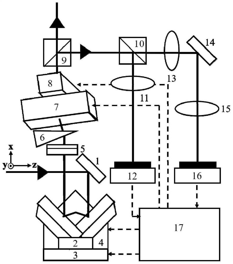
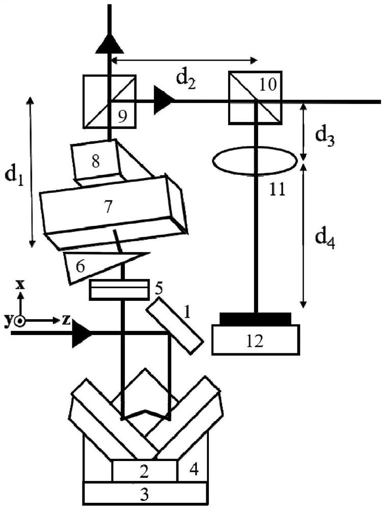
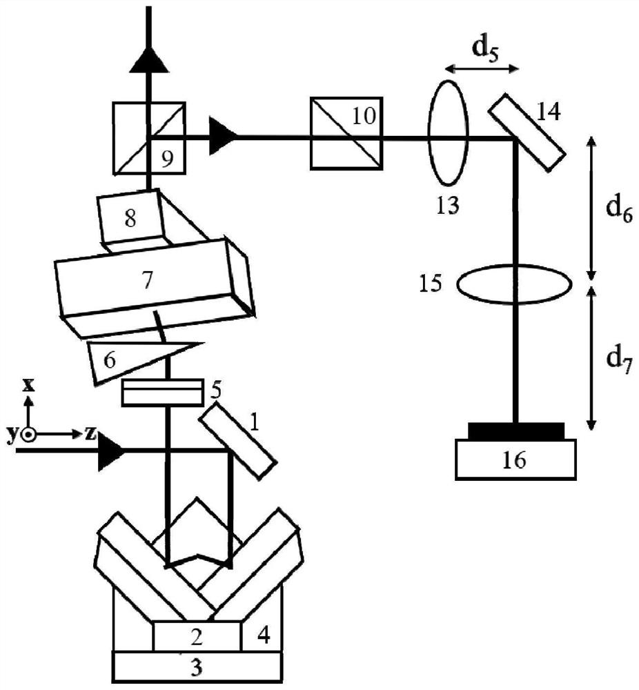
[0017] The present invention provides a beam stabilization device based on angle-free inertial feedback correction, such as figure 1 As shown, it includes a first reflective prism 1, a hollow retroreflector 2, a first nanomobile stage 3, a second nanomobile stage 4, a first prism 5, a second prism 6, a first beam deflector 7, and a second beam deflector Deflector 8, first dichroic prism 9, second dichroic prism 10, first lens 11, first photoelectric sensor 12, second lens 13, second reflector 14, third lens 15, second photoelectric sensor 16 , Controller 17.

[0018] use figure 1 The method for real-time stabilization of the incident light beam by the shown device is as follows:

[0019] An incident light beam with a wavelength of 532nm is incident on the hollow retroreflector 2 after ...


PUM


Abstract

The invention discloses a light beam stabilizing device based on angle inertia-free feedback correction. The device comprises a reflecting mirror, a hollow retroreflector, a nanometer displacement table, a triangular prism, an acousto-optic deflector, a beam splitter, a lens, a position detector, a controller and the like. According to the invention, a non-mechanical control method based on the acousto-optic deflector is used for replacing a mechanical control mode in a conventional system, so that the influence of inertial errors is avoided, and the interference of environmental noise is reduced. The advantage of high response frequency (which can reach more than 1MHz) of the acousto-optic deflector is utilized to realize rapid and high-precision beam angle drift correction. The stable light beam adjusted by the method and the device can be widely applied to a super-resolution microscopic imaging system and a high-precision laser direct writing photoetching system.

Description

technical field [0001] The invention belongs to the field of ultra-precision optical imaging and writing, and in particular relates to a light beam stabilization device based on angle-free inertial feedback correction. Background technique [0002] With the continuous breakthrough of the limit capability of laser technology, the precision requirements of the optical system are also continuously improved, so while the laser technology is widely used, it also faces a new problem - the problem of beam drift. The factors causing beam drift are complex and numerous, such as external mechanical drift, air disturbance in the system, changes in ambient temperature, and drift of the light source itself, etc., will all lead to irregular small movements of the beam in spatial position and angle. Moreover, the final drift effect of the beam is the superposition effect of all the above factors. In order for the system to achieve the desired effect, it is generally necessary to create a ...

Claims


Application Information

Patent Timeline
IPC IPC(8): G02F1/29G02F1/33G02B21/00G03F7/20
CPCG02F1/29G02F1/33G02B21/00G03F7/70216G03F7/2053
Inventor 丁晨良匡翠方杨臻垚孙秋媛刘旭徐良
Owner ZHEJIANG LAB
Why Eureka
Try Eureka