Al technical title is built by PatSnap Al team. It summarizes the technical point description of the patent document.
An environmentally friendly and energy-saving greenhouse technology, applied in the field of greenhouses, can solve the problems of overheating, lower power generation efficiency, and high installation location, and achieve the effects of reducing heat loss to the external environment, ensuring respiration, and high-efficiency photovoltaic power generation
Inactive Publication Date: 2022-01-11
鲁娜
View PDF0 Cites 0 Cited by
Summary
Abstract
Description
Claims
Application Information
AI Technical Summary
This helps you quickly interpret patents by identifying the three key elements:
Problems solved by technology
Method used
Benefits of technology
Problems solved by technology
[0002] With the maturity of photovoltaic power generation technology, photovoltaic panels have been promoted and installed on the top of many buildings for power generation. In recent years, photovoltaic panels have also begun to be laid on the top of some vegetable greenhouses with concrete or steel structures. Most of the photovoltaic panels laid on the top of vegetable greenhouses are fixed structures, which can only generate electricity, and because of their high installation position, they are prone to problems of inconvenient cleaning after long-term use, while the movable photovoltaic panels installed on vegetable greenhouses Although it can shade the crops in the greenhouse in high temperature weather, it cannot solve the problem of overheating caused by strong sunlight, and the overheating of photovoltaic panels will reduce the power generation efficiency, highlighting its shortcomings
Method used
Image
Click on the blue label to locate the original text in one second.
Reading with bidirectional positioning of images and text.
Examples
Embodiment Construction
[0018] The present invention will be further elaborated below in conjunction with the accompanying drawings and specific embodiments.
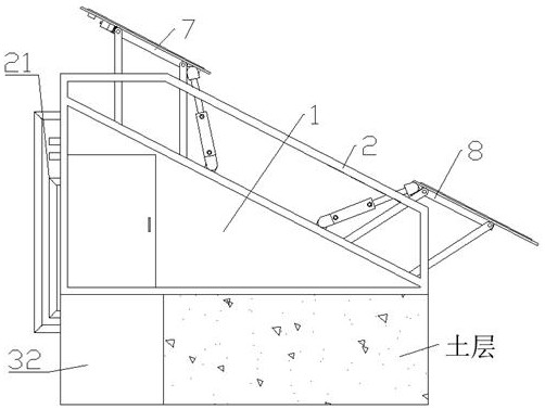
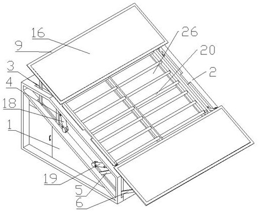
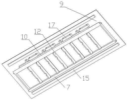
[0019] Such as Figure 1-6 As shown, an environmentally friendly and energy-saving greenhouse, including a wall 1, a support frame 2, a No. 1 swing rod 3, a No. 2 swing rod 4, a No. 3 swing rod 5, a No. 4 swing rod 6, an upper mounting frame 7, and a lower mounting frame 8. Heat conduction plate 9, rack frame 10, support shaft 11, heat dissipation plate 12, gear 13, arc groove 14, fill light belt 15, photovoltaic panel 16, No. 1 linear cylinder 17, No. 2 linear cylinder 18, three No. linear cylinder 19, heat exchange part 20, ventilation part 21, the front and rear ends of the wall 1 are respectively fixed with a support frame 2, and the two support frames 2 are sequentially hinged with a No. 1 swing rod 3 and No. 2 Swing rod 4, No. 3 swing rod 5 and No. 4 swing rod 6, the upper mounting bracket 7 is jointly hinged between the two described N...
PUM
Abstract
The invention discloses an environment-friendly energy-saving greenhouse. The greenhouse comprises a wall body, supporting frames, a first swing rod, a second swing rod, a third swing rod, a fourth swing rod, an upper mounting frame, a lower mounting frame, a heat conduction plate, a rack frame, a supporting shaft, a heat dissipation plate, a gear, an arc-shaped groove, a light supplementing lamp belt, a photovoltaic panel, a first linear air cylinder, a second linear air cylinder, a third linear air cylinder, a heat exchange part and a ventilation part. The supporting frames are fixed to the front end and the rear end of the wall body correspondingly, and the two supporting frames are sequentially hinged to a first swing rod, a second swing rod, a third swing rod and a fourth swing rod from top to bottom. The environment-friendly energy-saving greenhouse has the functions of efficient photovoltaic power generation, multi-effect heat exchange and yield increase at the same time, under the high-temperature and strong-light environment, the heat dissipation plate is controlled to be unfolded, then the arc-shaped groove is in contact with a heat exchange pipe, the purposes of cooling the photovoltaic panel and increasing the temperature of the heat exchange pipe are achieved, the photovoltaic panel can fully receive illumination all the time, and therefore the efficient power generation function can be achieved.
Description
technical field [0001] The invention relates to a greenhouse, in particular to an environment-friendly and energy-saving greenhouse. Background technique [0002] With the maturity of photovoltaic power generation technology, photovoltaic panels have been promoted and installed on the top of many buildings for power generation. In recent years, photovoltaic panels have also begun to be laid on the top of some vegetable greenhouses with concrete or steel structures. Most of the photovoltaic panels laid on the top of vegetable greenhouses are fixed structures, which can only generate electricity, and because of their high installation position, they are prone to problems of inconvenient cleaning after long-term use, while the movable photovoltaic panels installed on vegetable greenhouses Although photovoltaic panels can shade the crops in the greenhouse in high temperature weather, they cannot solve the problem of overheating caused by strong sunlight. Overheating of photovolt...
Claims
Application Information
Patent Timeline
Application Date:The date an application was filed.
Publication Date:The date a patent or application was officially published.
First Publication Date:The earliest publication date of a patent with the same application number.
Issue Date:Publication date of the patent grant document.
PCT Entry Date:The Entry date of PCT National Phase.
Estimated Expiry Date:The statutory expiry date of a patent right according to the Patent Law, and it is the longest term of protection that the patent right can achieve without the termination of the patent right due to other reasons(Term extension factor has been taken into account ).
Invalid Date:Actual expiry date is based on effective date or publication date of legal transaction data of invalid patent.