
Threading robot for building electrical construction

A construction electrical and robotic technology, applied in the field of threading robots, can solve the problems of looseness, entanglement of traction wires and cables, and intricate traction wires.

Inactive Publication Date: 2022-01-07
CHINA RAILWAY URBAN PLANNING & DESIGN INST
View PDF3 Cites 0 Cited by
  • Summary
  • Abstract
  • Description
  • Claims
  • Application Information

AI Technical Summary

Problems solved by technology

[0003] When threading the wires, the construction personnel generally manually insert the traction wire into the pre-embedded pipe. Pull back the traction line at one point, and the traction line will be stacked on the ground after being pulled back, and the traction line will be intricately entangled. The force is different when pulling the cable. Long-term restraint will loosen and separate the connection between the pulling cable and the cable, resulting in the cable being stuck inside the pipe and unable to move forward.

Method used


Image

  • Threading robot for building electrical construction
  • Threading robot for building electrical construction
  • Threading robot for building electrical construction

Examples


Embodiment 1

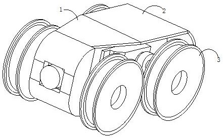
[0030] see figure 1 , the present invention provides a technical solution: a threading robot for building electrical construction, its structure includes a winding device 1, a body 2, and a moving wheel 3, the winding device 1 is connected to the body 2, and the body 2 is connected to the body 2 Both sides of the winding device 1 are provided with moving wheels 3 .

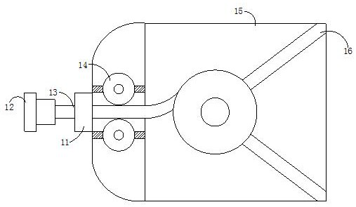
[0031] see figure 2 , the rewinding device 1 includes an interface 11, a docking fastener 12, a pulling wire 13, an auxiliary guide 14, a cavity 15, and a rewinding assembly 16, the interface 11 is fixedly connected to the cavity 15, and the cavity A winding assembly 16 is installed inside the body 15, and the winding assembly 16 is connected to the pulling wire 13, and the pulling wire 13 is connected to the interface 11 through the auxiliary guide 14, and the pulling wire 13 is connected to two auxiliary Between the guides 14, the traction line 13 is inserted and connected to the docking fastener 12, the cav...

Embodiment 2

[0038] see figure 1 , the present invention provides a technical solution: a threading robot for building electrical construction, its structure includes a winding device 1, a body 2, and a moving wheel 3, the winding device 1 is connected to the body 2, and the body 2 is connected to the body 2 Both sides of the winding device 1 are provided with moving wheels 3 .

[0039] see figure 2 , the rewinding device 1 includes an interface 11, a docking fastener 12, a pulling wire 13, an auxiliary guide 14, a cavity 15, and a rewinding assembly 16, the interface 11 is fixedly connected to the cavity 15, and the cavity A winding assembly 16 is installed inside the body 15, and the winding assembly 16 is connected to the pulling wire 13, and the pulling wire 13 is connected to the interface 11 through the auxiliary guide 14, and the pulling wire 13 is connected to two auxiliary Between the guides 14, the traction line 13 is inserted and connected to the docking fastener 12, the cav...


PUM


Abstract

The invention discloses a threading robot for building electrical construction. The threading robot structurally comprises a winding device, a machine body and moving wheels. When the threading robot is used, one end of a pull wire is clamped on a butt-joint fastener in a penetrating manner, the butt-joint fastener drives the pull wire to extend into a pre-buried pipeline, and a winding assembly can rotate along with the extension of the pull wire; the pull wire is guided out through the matched rotation of the two auxiliary guide pieces, so that the pull wire is not prone to retracting inwards when extending outwards; after the pull wire stretches out of the pre-buried pipeline, the pull wire is in fastening butt joint with a cable through the butt joint fastener, and after butt joint, the winding assembly is controlled through a controller in the machine body, so that the winding assembly can be recycled in the opposite direction, the pull wire is taken back, and the cable is effectively pulled to pass through the pipe at a uniform speed.

Description

technical field [0001] The invention relates to the technical field of building electrical construction, in particular to a threading robot for building electrical construction. Background technique [0002] Building electrical includes electrical systems such as power supply, lighting, and telephone fire protection. During the installation and construction of these electrical systems, cables need to be laid in advance, such as wires and signal lines. The cable is inserted into the wire tube, and the wire and the pull wire are butted together through the docking element. When threading the wire, the areas that need improvement: [0003] When threading the wires, the construction personnel generally manually insert the traction wire into the pre-embedded pipe. Pull back the traction line at one point, and the traction line will be stacked on the ground after being pulled back, and the traction line will be intricately entangled. Pull the wire with different forces, and long...

Claims


Application Information

Patent Timeline
Patent Type & Authority Applications(China)
IPC IPC(8): H02G1/08H02G11/02
CPCH02G1/081H02G11/02
Inventor 闫化冰葛晓峰
Owner CHINA RAILWAY URBAN PLANNING & DESIGN INST
Learn More