


Quick Research
Generate reliable direction feasibility study reports for your R&D in just a few steps.

Technical Q&A
Discover and master advanced knowledge NOW. Basics, ideas, possibilities, all at once.

Find Solutions
As an expert in R&D theories, this can generate solutions to your technical problems instantly.

Evaluate Feasibility
Analyze your overall solution with one click, know your potential R&D risks in advance.

Monitor Landscape
Get weekly tech updates, stay abreast of the latest tech innovations and key insights.
Display unit correction method and device and computer readable storage medium
A technology of display unit and calibration method, applied to static indicators, instruments, etc., to achieve the effect of improving calibration efficiency
- Summary
- Abstract
- Description
- Claims
- Application Information
AI Technical Summary
Problems solved by technology
Method used
Image

Examples
no. 1 example
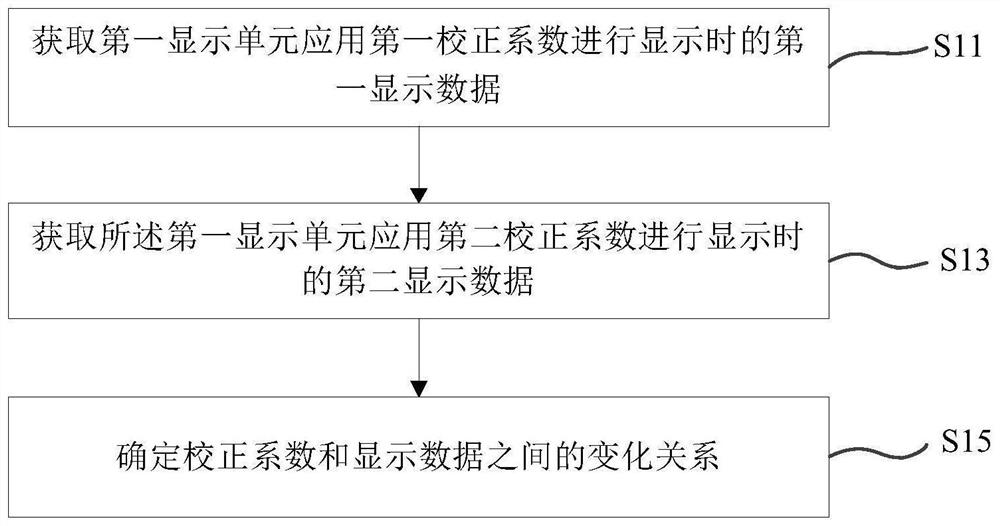
[0053] see figure 1 , the first embodiment of the present invention discloses a display unit calibration method. For example, the display unit calibration method can be applied to low-gray uniformity correction, or the display unit calibration method can be applied to uniformity calibration when the brightness of the display unit is lower than the first threshold or lower than the first gray scale. Such as figure 1 As shown, the display unit calibration method includes, for example:
[0054] S11: Acquire first display data when the first display unit applies the first correction coefficient to display;
[0055] Optionally, the display unit herein may be a light panel, a box, a module or other units that can be used for display.
[0056] For example, the display unit may be a light panel, a box, or a unit spliced by at least one light panel or a unit spliced by at least one box.
[0057] S13: Obtain second display data when the first display unit applies the second corr...
no. 2 example
[0158] Such as Figure 9 As shown, an embodiment of the present invention discloses a display unit calibration apparatus 200 for implementing a display unit calibration method disclosed in the aforementioned first embodiment. For example, the display unit calibration device 200 includes: a first display data acquisition module 210 , a second display data acquisition module 220 , and a change relationship determination module 230 .
[0159] Wherein, the first display data acquisition module 210 is configured to acquire the first display data when the first display unit applies the first correction coefficient for display. The second display data obtaining module 220 is configured to obtain the second display data when the first display unit applies the second correction coefficient for display. The change relationship determination module 230 is used to determine the change relationship between the correction coefficient and the display data, the change relationship is used to...
no. 3 example
[0162] In addition, if Figure 10 As shown, the third embodiment of the present invention discloses a display cabinet calibration system 300 , for example including: a processor 310 and a memory 320 connected to the processor 310 . The memory 320 stores instructions executed by the processor 310, and the instructions cause the processor 310 to perform operations to perform the display unit calibration method described in the foregoing embodiments. For the specific implementation process and functions of the display unit calibration system 300 in the embodiment of the present invention, reference may be made to the description of the foregoing first embodiment, and details are not repeated here.
PUM
 Abstract
Description
Claims
Application Information
 - R&D Engineer
- R&D Manager
- IP Professional
- Industry Leading Data Capabilities
- Powerful AI technology
- Patent DNA Extraction
Browse by: Latest US Patents, China's latest patents, Technical Efficacy Thesaurus, Application Domain, Technology Topic, Popular Technical Reports.
© 2024 PatSnap. All rights reserved.Legal|Privacy policy|Modern Slavery Act Transparency Statement|Sitemap|About US| Contact US: help@patsnap.com