
Heat-resistant material drilling device

A heat-resistant material and drilling technology, which is used in metal processing machinery parts, maintenance and safety accessories, metal processing equipment, etc., can solve the problems of ineffective coolant, difficult to discharge drilling chips, and high temperature of the drill bit, saving manpower, The process of evaporation and heat absorption is fast and the heat dissipation effect is good.

Pending Publication Date: 2022-01-07
高力功
View PDF0 Cites 0 Cited by
  • Summary
  • Abstract
  • Description
  • Claims
  • Application Information

AI Technical Summary

Problems solved by technology

[0004] Aiming at the deficiencies of the prior art, the present invention provides a heat-resistant material drilling device, which solves the problem that the drill bits are difficult to discharge when the drill bit is drilling wear-resistant materials due to the limitation of the material properties of the heat-resistant material itself. The coolant cannot act on the drill bit, which makes the temperature of the drill bit higher and the wear is more serious.

Method used


Image

  • Heat-resistant material drilling device
  • Heat-resistant material drilling device
  • Heat-resistant material drilling device

Examples


Embodiment 1

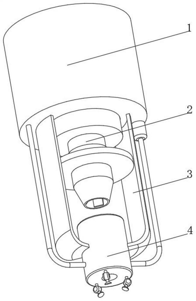
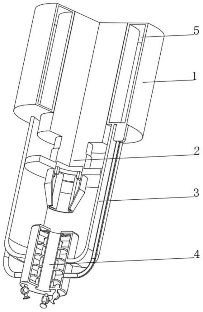
[0034] see Figure 1-4 , the present invention provides a technical solution: a heat-resistant material drilling device, specifically comprising:

[0035] The fixed seat 1, the bottom of the fixed seat 1 is connected with the tool fixed seat 2 through the rotating shaft, the top of the tool fixed seat 2 is fixedly connected with the drive shaft of the external motor through the rotating shaft, and the inside of the fixed seat 1 is provided with a coolant storage tank 5;

[0036] Bracket 3, the bracket 3 is arranged at the bottom of the fixing seat 1 on both sides of the tool fixing seat 2, and the bottom of the bracket 3 is fixedly connected with a cooling device 4;

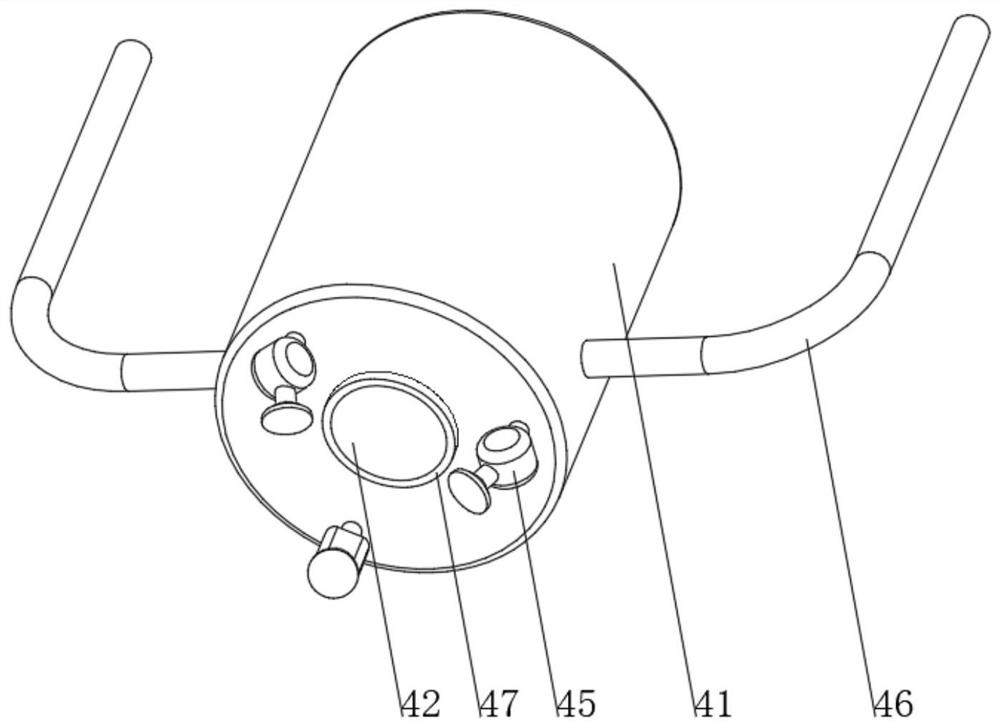
[0037] Cooling device 4 comprises:

[0038] Cooling cylinder 41, the top and bottom of the cooling cylinder 41 are provided with a through hole 42, the inner wall of the through hole 42 is connected to the limit ring 47 through bearing rotation, and the two sides of the cooling cylinder 41 are connected with a c...

Embodiment 2

[0046] see Figure 1-5 On the basis of Embodiment 1, the present invention provides a technical solution: the nozzle device 45 includes a liquid outlet pipe 451, one end of the liquid outlet pipe 451 is connected with a fixed disk 452, one side of the fixed disk 452 is connected with a rotating disk 453, and the fixed disk 452 The inner wall and the outer wall of the rotating disk 453 are rotationally connected by sealed bearings. One side of the rotating disk 453 is connected with a nozzle 454, and the end of the nozzle 454 far away from the rotating disk 453 is connected with an atomizing nozzle 455. The nozzle device 45 is provided with multiple groups and uniform Distributed at the bottom of the cooling cylinder 41 , the top of the outlet pipe 451 communicates with the interior of the cooling cylinder 41 , and a damping pad is provided between the fixed disk 452 and the rotating disk 453 .

[0047] A nozzle device 45 is provided. When the pressure inside the cooling cylind...


PUM


Abstract

The invention relates to the technical field of drilling, and discloses a heat-resistant material drilling device which particularly comprises a fixing seat and brackets, wherein a cutter fixing seat is rotationally connected with the bottom of the fixing seat through a rotating shaft; the top of the cutter fixing seat is fixedly connected with a driving shaft of an external motor through the rotating shaft; a cooling liquid storage box is arranged in the fixing seat; the brackets are arranged at the bottom of the fixing seat and positioned on two sides of the cutter fixing base, of the bottom of the fixing base; a cooling device is fixedly connected with the bottoms of the brackets, and comprises a cooling cylinder and a heat-conductive sleeve; through holes are formed in both the top and the bottom of the cooling cylinder; limiting rings are rotationally connected with the inner walls of the through holes through bearings; and circulating pipes communicate with two sides of the cooling cylinder. According to the heat-resistant material drilling device, the heat-dissipating effect on a drill bit is relatively good; the situation that a cooling liquid is thrown out when the drill bit rotates because the cooling liquid on the drill bit is excessive can be avoided; and the situation that a working table top is polluted by the cooling liquid can be avoided.

Description

technical field [0001] The invention relates to the technical field of drilling, in particular to a heat-resistant material drilling device. Background technique [0002] Drilling is a basic method of hole processing. Drilling is often carried out on drilling machines and lathes, and can also be carried out on boring machines or milling machines. Commonly used drilling machines include bench drilling machines, vertical drilling machines and radial drilling machines. Drilling machines are used for hole processing. The main machine tool, on the drilling machine, the drill bit (twist drill) is mainly used for drilling. When drilling on the lathe, the workpiece rotates and the tool performs the feed motion. However, when processing on a drilling machine, the workpiece does not move, and the tool performs the main motion of rotation, and at the same time moves along the axial direction for feed motion. Therefore, the drilling machine is suitable for processing holes on workpiece...

Claims


Application Information

Patent Timeline
IPC IPC(8): B23Q11/00
CPCB23Q11/00
Inventor 高力功
Owner 高力功
Learn More