Eureka AIR delivers breakthrough ideas for toughest innovation challenges, trusted by R&D personnel around the world.

Porous and micropore combined throttling gas static pressure turning electric spindle

A gas static pressure, porous technology, applied in the direction of manufacturing tools, metal processing machinery parts, positioning devices, etc., can solve the problems of small bearing capacity, long pressurized gas flow, reduced rigidity of the static pressure spindle, etc., to improve the bearing capacity Effects of force and stiffness, reduced self-excited vibrations, reduced risk of clogging

Active Publication Date: 2022-01-07
INST OF MACHINERY MFG TECH CHINA ACAD OF ENG PHYSICS
View PDF8 Cites 3 Cited by
  • Summary
  • Abstract
  • Description
  • Claims
  • Application Information

AI Technical Summary

Problems solved by technology

However, the pore diameter of the tiny pores inside the existing porous material is very small, the pore diameter is generally a few microns or even smaller, the material permeability is small, and the flow resistance is large, resulting in low bearing capacity and low stiffness of the bearing.
Furthermore, the distribution of tiny pores inside the porous material is chaotic, the flow channel bends irregularly, the flow of pressurized gas is longer, and the bearing responds slowly to dynamic loads
In addition, the tiny pores of porous materials are easy to block during material processing and bearing operation, resulting in a decrease in the stiffness of the porous throttling aerostatic spindle or even a locking phenomenon, which affects the reliability of ultra-precision lathes

Method used


Image

  • Porous and micropore combined throttling gas static pressure turning electric spindle
  • Porous and micropore combined throttling gas static pressure turning electric spindle
  • Porous and micropore combined throttling gas static pressure turning electric spindle

Examples


Embodiment

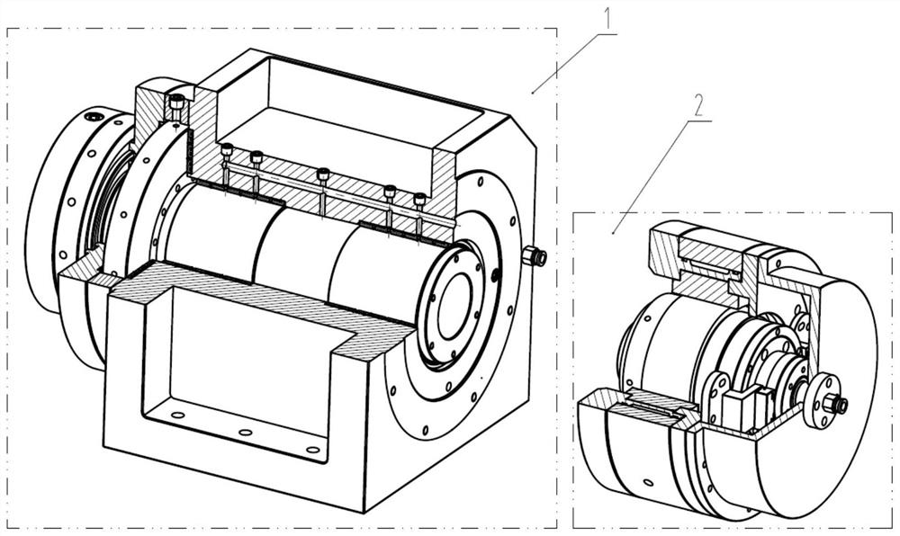
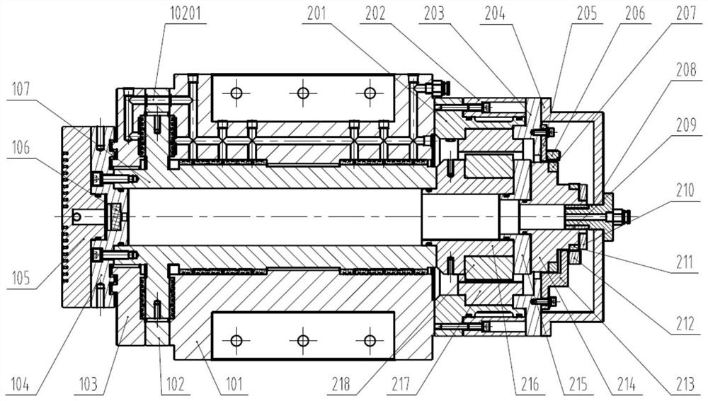
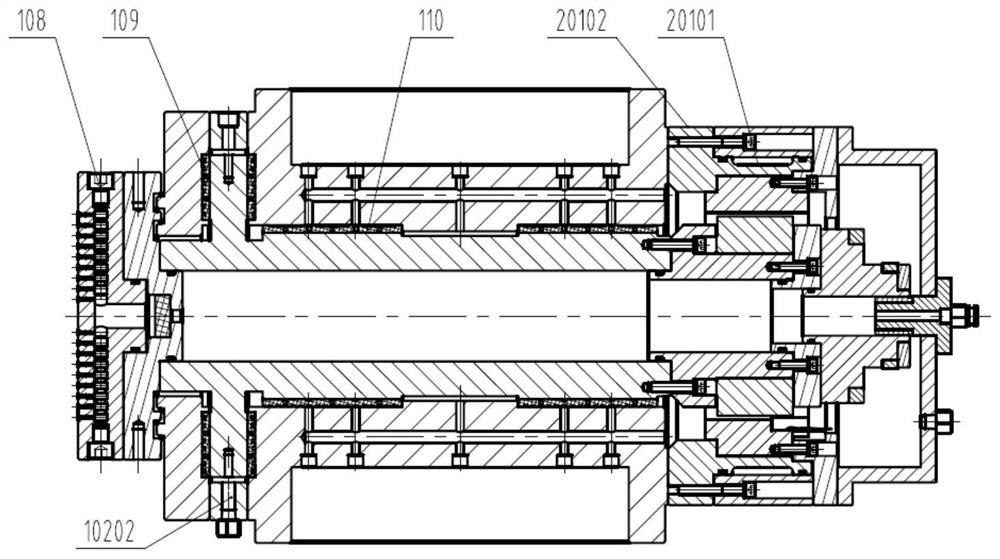
[0045] This embodiment combines the attached Figure 1-15 The porous and microporous combined throttling aerostatic turning electric spindle of the present invention will be described in detail.

[0046] The porous and microporous combined throttling gas static pressure turning electric spindle of the present invention includes an air bearing assembly 1 and a driving assembly 2, wherein figure 1 The left figure in the figure is a structural schematic diagram of the air bearing assembly 1, figure 1 The right figure in the figure is a structural schematic diagram of the drive assembly 2; the air bearing assembly 1 is composed of a base 101, a backing ring 102, a thrust plate 103, a debris plate 104, a suction cup 105, a filter plug 106, a rotating shaft 107, and two air blocking Composed of rod 108, 2 axial restrictors 109 and 2 radial restrictors 110, drive assembly 2 consists of stator mounting part 201, cooling sleeve 202, stator pressure plate 203, protective sleeve 204, gr...


PUM


Abstract

The invention discloses a porous and micropore combined throttling gas static pressure turning electric spindle which comprises a gas floating supporting assembly, wherein the gas floating supporting assembly comprises a rotating shaft, the rotating shaft is sequentially provided with a rotating shaft axial supporting section, a rotating shaft radial first supporting section and a rotating shaft radial second supporting section in the direction from one end to the other end of the rotating shaft, and axial throttlers are arranged on the two sides of the rotating shaft axial supporting section; radial throttlers are arranged on the rotating shaft radial first supporting section and the rotating shaft radial second supporting section; a plurality of annular gas supply grooves are formed in the outer side of the axial throttler in the axial direction and the outer side of the radial throttler in the radial direction, a plurality of transition gas supply holes are formed in at least one gas supply groove, and throttling micropores are formed in the transition gas supply holes. According to the scheme, through the combined throttling effect of the inherent tiny holes of the porous material and the additionally-formed throttling micropores, a supporting gas film can obtain large bearing capacity and rigidity, and the static and dynamic characteristics of a turning spindle are improved.

Description

technical field [0001] The invention relates to the technical field of precision cutting, in particular to a porous and micropore combined throttling gas static pressure turning electric spindle. Background technique [0002] The gas static pressure bearing is lubricated and supported by the gas film formed by the external pressurized gas in the gap of the rotating pair. It has the advantages of high motion precision, fast rotation speed, low power consumption, low heat generation, and long service life. It is the first choice for ultra-precision lathe spindles. In order to carry the parts for rotary motion and resist the dynamic cutting force during machining, the aerostatic spindle of ultra-precision lathes needs to have sufficient bearing capacity and rigidity. Throttling the external pressurized gas is the key link for gas static pressure bearings to obtain bearing capacity and stiffness. Common throttling methods include small hole throttling, gap throttling, annular t...

Claims


Application Information

Patent Timeline
Patent Type & Authority Applications(China)
IPC IPC(8): B23B19/02B23Q3/12
CPCB23Q1/70B23Q3/12B23Q2703/04
Inventor 陈刚利黄明崔海龙郑越青冯艳冰夏欢张新疆龚维纬钱林弘张小强
Owner INST OF MACHINERY MFG TECH CHINA ACAD OF ENG PHYSICS
Why Eureka
Eureka Blog
Learn More