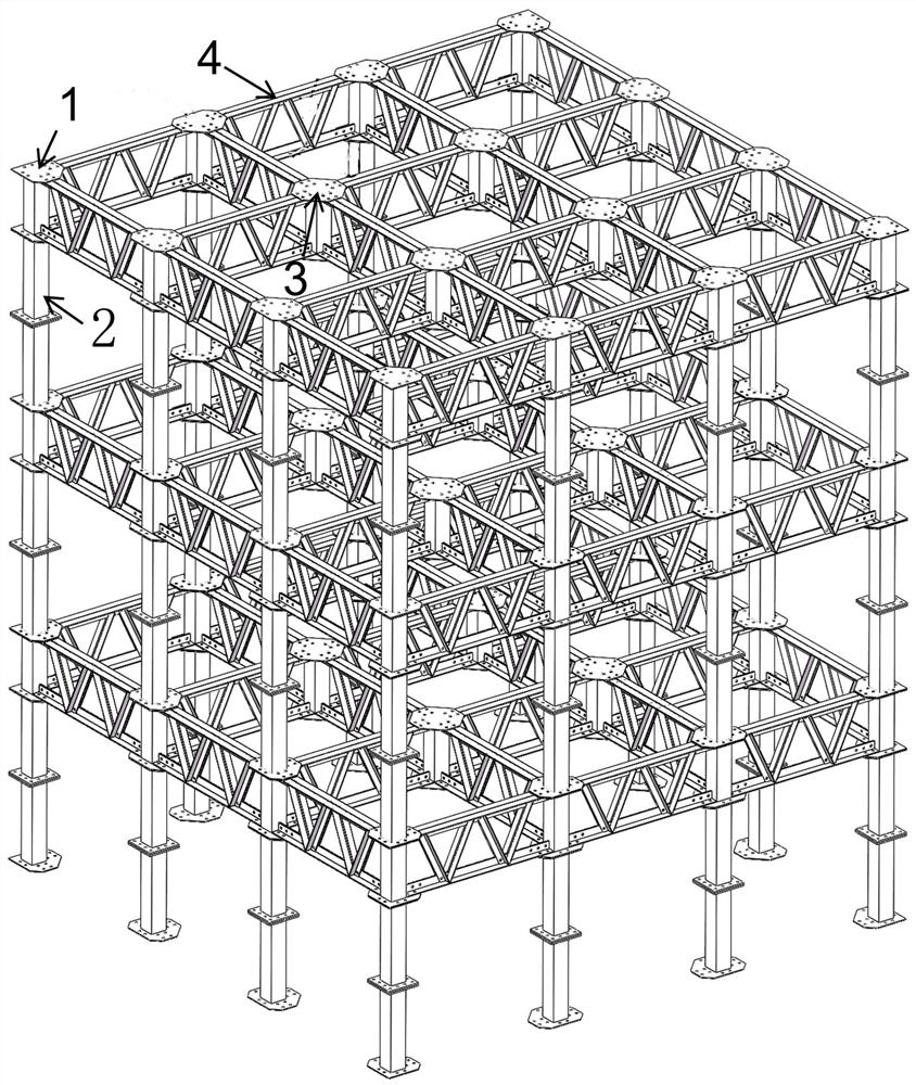
Fabricated truss girder steel beam tube structure system adopting full bolt connection
A truss beam, prefabricated technology, applied in structural elements, building components, building structures, etc., can solve the problems of difficult construction, difficult transportation of steel trusses, and large amount of work at high altitudes, and achieves short construction period and fast construction and assembly. Convenience and the effect of improving the assembly rate
- Summary
- Abstract
- Description
- Claims
- Application Information
AI Technical Summary
Problems solved by technology
Method used
Image
Examples
Embodiment 1
[0031] Embodiment 1: This embodiment aims to provide a prefabricated truss beam steel beam tube structure system that adopts full bolt connection, which is mainly used for prefabricated truss structures. For existing equipment, bolt welding connections are mostly used, and the overall assembly has a low degree of disassembly , some parts are damaged and cannot be replaced, and the overall assembly and transportation costs are high, and construction is difficult. Based on this, this embodiment provides an assembled truss beam steel beam tube structure system that adopts full bolt connections.
[0032] Such as figure 1 As shown in , a prefabricated truss girder steel beam tube structure system using full bolt connection, including truss beam unit 4, column unit and node unit; The node units are connected with the column units, and the column units are distributed on the periphery and are at the same elevation.
[0033] In a specific implementation, the truss beam unit 4 include...
Embodiment 2
[0042] Embodiment 2: This embodiment is basically the same as Embodiment 1, and the difference is that this embodiment further explains the structure of the connecting column 2 .
[0043] In this embodiment, the connecting column 2 includes an upper connecting column 21 and a lower connecting column 22 that can be butt-connected together, wherein the upper end of the upper connecting column 21 is provided with a connecting plate 23, and its lower end is provided with a docking plate 24. The lower end is provided with a connecting plate, and the upper end is provided with a butt plate 24, and the two butt plates are adapted and provided with corresponding through holes.
[0044] In this embodiment, the connecting column is a detachable structure. During the specific construction, the upper connecting column 21 and the lower connecting column 22 are respectively connected with the side node column 1, and the truss beam unit is assembled and connected with the middle node column, ...
Embodiment 3
[0046] Embodiment 3: This embodiment is basically the same as Embodiment 1, the difference is that in this embodiment, there are too many connecting bolts between the upper connecting column and the lower connecting column, and most of them are in the high-altitude operation state, so the construction is difficult and the work For the problem of large quantity, the present embodiment sets up a bolt fixing frame and a nut fixing frame to reduce the problem of difficult bolt construction in the process of working at heights.
[0047] In the specific structure, the present embodiment is provided with a bolt fixing frame 5 on the upper connecting column, and the bolt fixing frame 5 includes an upper fixing sleeve 51, a top screw 52 and a connecting bolt 53; the upper fixing sleeve 51 is matched and set on the upper connecting column 21 , its side is provided with the top wire 52 that runs through its side wall, the position of the upper fixed sleeve 21 can be fixed by the top wire ...
PUM
 Abstract
Description
Claims
Application Information
 - R&D
- Intellectual Property
- Life Sciences
- Materials
- Tech Scout
- Unparalleled Data Quality
- Higher Quality Content
- 60% Fewer Hallucinations
Browse by: Latest US Patents, China's latest patents, Technical Efficacy Thesaurus, Application Domain, Technology Topic, Popular Technical Reports.
© 2025 PatSnap. All rights reserved.Legal|Privacy policy|Modern Slavery Act Transparency Statement|Sitemap|About US| Contact US: help@patsnap.com


