Low-cost light-small medium-wave infrared continuous zooming optical system

An optical system, light and small technology, used in optics, optical components, instruments, etc., to improve imaging quality, shorten the axial size of the system, and reduce the size

Pending Publication Date: 2021-12-31
KUNMING INST OF PHYSICS
View PDF15 Cites 1 Cited by
  • Summary
  • Abstract
  • Description
  • Claims
  • Application Information

AI Technical Summary

Problems solved by technology

Cooled infrared continuous zoom optical syste

Method used


Image

  • Low-cost light-small medium-wave infrared continuous zooming optical system
  • Low-cost light-small medium-wave infrared continuous zooming optical system
  • Low-cost light-small medium-wave infrared continuous zooming optical system

Examples


Embodiment 1

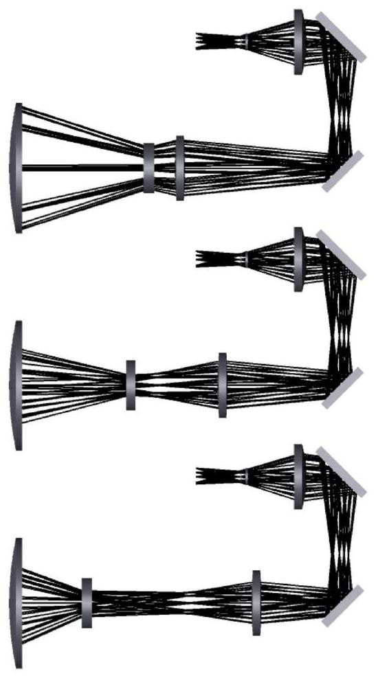
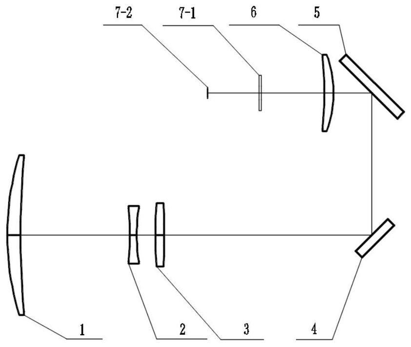
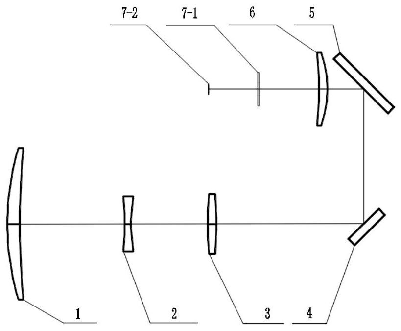
[0040] The low-cost, light and small medium-wave infrared continuous zoom optical system provided by the present invention, such as figure 2 As shown, in the direction of the optical axis determined by the mid-wave infrared light path radiated by the scene object, it is set in sequence from the object side to the image side: as the positive power meniscus lens 1 of the front fixed group, as the variable magnification Negative power biconcave lens 2 as a group, positive power biconvex lens 3 as a compensation group, no power plane mirror 4, no power plane mirror 5, positive power meniscus lens as a medium dimension group 6. The window 7-1 of the medium-wave cooling detector is imaged on the focal plane 7-2 of the medium-wave cooling detector; so that the light of the target scene passes through the positive power meniscus lens 1 of the front fixed group, and the negative power of the zoom group Biconcave lens 2, biconvex lens with positive dioptric power in the compensation gr...

Embodiment 2

[0061] The low-cost, light and small medium-wave infrared continuous zoom optical system provided by the present invention, such as figure 2 As shown, in the direction of the optical axis determined by the mid-wave infrared light path radiated by the scene object, it is set in sequence from the object side to the image side: as the positive power meniscus lens 1 of the front fixed group, as the variable magnification Negative power biconcave lens 2 for the group, positive power biconvex lens 3 as the compensating group, aphotic plane mirror 4, aphotic plane mirror 5, positive power meniscus lens as the relay group 6. The window 7-1 of the medium-wave cooling detector is imaged on the focal plane 7-2 of the medium-wave cooling detector; so that the target scene light passes through the positive focal power meniscus lens 1 of the front fixed group, and the negative focal power of the variable power group Biconcave lens 2, biconvex lens with positive dioptric power in compensati...


PUM


Abstract

The invention relates to a low-cost light-small medium-wave infrared continuous zooming optical system, which is characterized in that: in an optical axis direction determined on a medium-wave infrared light path radiated by a scenery target, a positive focal power meniscus lens serving as a front fixing group, a negative focal power biconcave lens serving as a zoom group, a positive focal power biconvex lens serving as a compensation group, a non-focal power plane mirror, a non-focal power plane mirror, a positive focal power meniscus lens serving as a relay group and a refrigeration medium wave detector are sequentially arranged from an object side to an image side, and light is imaged on a focal plane of the medium-wave refrigeration detector. The 10-time continuous zooming function of an infrared optical system is achieved, the number of lenses is reduced, the axial size of the system is shortened, the weight and cost are reduced, 100% cold screen efficiency is achieved, the imaging quality is improved, good imaging quality is kept within the range of -40 DEG C to 60 DEG C, and athermalization, low cost, light weight, small size and high performance are achieved.

Description

technical field [0001] The invention belongs to the technical field of optical imaging, and in particular relates to a cooling type mid-wave infrared continuous zoom optical system mainly used in hand-held infrared cameras, vehicle-mounted infrared cameras, airborne infrared cameras and the like. Background technique [0002] In recent years, with the rapid development of infrared cooling detectors in the direction of small size, light weight, low power consumption, that is, low SWaP (Size, Weight and Power), such mid-wave infrared detectors integrated with small refrigerators have been widely used in weapon thermal Space-limited infrared systems such as scopes, portable handheld thermal imagers, small drones, unmanned vehicles, remote-controlled snipers and remote-controlled weapon stations, and missile seekers. Designing a light-weight, small-sized, and low-cost mid-wave infrared continuous zoom optical system composed of only four lenses for this type of small detector ca...

Claims


Application Information

Patent Timeline
IPC IPC(8): G02B15/14G02B13/00G02B13/14
CPCG02B15/144113G02B13/004G02B13/008G02B13/009G02B13/14Y02A90/10
Inventor 唐晗曹凌徐曼明景谦曾兴容季振波贾星蕊王海洋付艳鹏董海翔汪兴杨静
Owner KUNMING INST OF PHYSICS
Why Eureka
Try Eureka