Tin plating device and tin plating method for light-condensing welding strip

A technology of soldering strip and tin bath, which is applied in the direction of coating, metal material coating process, fusion spraying, etc., can solve the problems of inability to cool the soldering strip, long time for tinning the soldering strip, low efficiency, etc., and achieve a scientific structure Reasonable, safe and convenient to use, wide range of effects

Pending Publication Date: 2021-12-31
江阴市晨达新能源科技有限公司
View PDF0 Cites 0 Cited by
  • Summary
  • Abstract
  • Description
  • Claims
  • Application Information

AI Technical Summary

Problems solved by technology

[0003] Compared with the conventional ribbon, the front of the ribbon is coated with silver powder and other light-condensing materials. When the cell stringing process is performed, because the front coating does not contain tin, the front of the ribbon cannot be welded to the back of the cell normally.
Furthermore, it is necessary to tin-coat the solder strips. During the use of traditional tin-coating devices, the thickness of the tin-coated tin layer cannot be controlled, and the thickness of the tin-coated layer cannot be adjusted and controlled according to actual needs after the tin coating is completed, and In the process of tinning, it is not convenient to adjust the tension of the soldering strip. The stability of the soldering strip is poor in the process of tinning, and the effect of tinning is poor. At the same time, the soldering strip cannot be cooled quickly after tinning, so that It takes a long time to coat the entire soldering strip with low efficiency. Therefore, in order to solve this series of problems, we propose a tinning device and a tinning method for the concentrated soldering strip to solve the problem.

Method used


Image

  • Tin plating device and tin plating method for light-condensing welding strip
  • Tin plating device and tin plating method for light-condensing welding strip
  • Tin plating device and tin plating method for light-condensing welding strip

Examples


Embodiment Construction

[0024] The following will clearly and completely describe the technical solutions in the embodiments of the present invention with reference to the accompanying drawings in the embodiments of the present invention. Obviously, the described embodiments are only some, not all, embodiments of the present invention. Based on the embodiments of the present invention, all other embodiments obtained by persons of ordinary skill in the art without making creative efforts belong to the protection scope of the present invention.

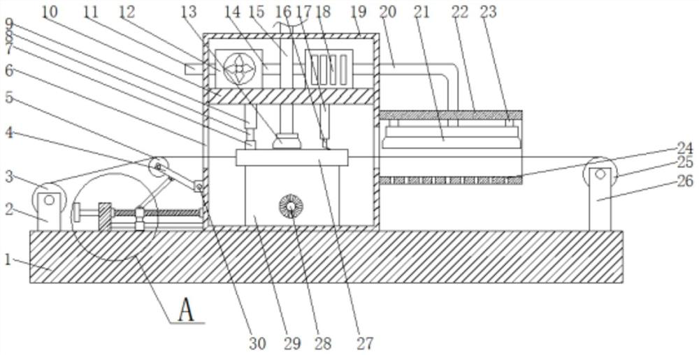
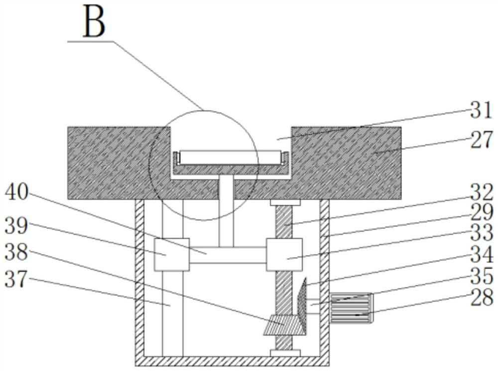
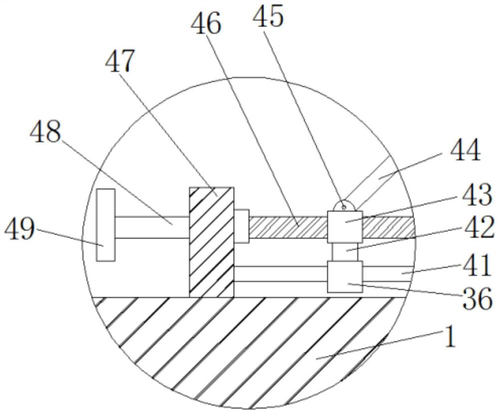
[0025] see Figure 1-4, the present invention provides a technical scheme: a technical scheme of a tin coating device and a tin coating method for a concentrating solder strip, comprising a base 1 and a tin coating box 19, the tin coating box 19 is fixedly installed on the top of the base 1, and on the side walls of the tin coating box 19 both sides Openings 6 are provided, one side of the top of the base 1 is provided with a first roller frame 2, the other si...


PUM


Abstract

The invention discloses a tin plating device and a tin plating method for a light-condensing welding strip. A base and a tin plating box are included, the tin plating box is fixedly installed at the top of the base, openings are formed in the side walls of the two sides of the tin plating box, a first roller frame is arranged at one side of the top of the base, and a third roller frame is arranged at the other side of the top of the base; and a wire guide roller is movably installed at one side of the top of the base through the first roller frame, and a winding roller is movably installed at the other side of the top of the base through the third roller frame. By means of the tin plating device and the tin plating method, the structure is scientific and reasonable, use is safe and convenient, the tension degree of the welding strip is conveniently adjusted before tin plating, then the tin plating effect of the welding strip is improved, and spraying is comprehensive; the tin plating thickness actually required by the welding strip can be adjusted, so that the tin plating device and the tin plating method are suitable for production and processing of welding strips with different tin layer thicknesses; and the welding strip obtained after tin plating can be quickly cooled by air, so that the welding strip obtained after tin plating can be quickly wound, and the tin plating efficiency of the whole welding strip is high.

Description

technical field [0001] The invention relates to the technical field of production and processing of concentrating welding strips, in particular to a tin coating device and a tin coating method for concentrating welding strips. Background technique [0002] Ribbon occupies an important position in the photovoltaic industry. It is applied to the connection between cells of photovoltaic modules and plays the role of conducting electricity and collecting electricity. The conventional ribbon has a flat surface due to the width of the ribbon and the surface of the ribbon. The light of the line part is blocked to a certain extent and cannot be reused. However, due to the reflection effect of the concentrating surface, the concentrating ribbon solves the shading problem of the conventional ribbon and improves the conversion efficiency of the photovoltaic module. The function of the belt is to reflect the sunlight directly on the ribbon through the concentrating surface, and the refl...

Claims


Application Information

Patent Timeline
IPC IPC(8): C23C4/123C23C4/08C23C4/14
CPCC23C4/123C23C4/08C23C4/14
Inventor 刘江
Owner 江阴市晨达新能源科技有限公司
Why Eureka
Try Eureka