
Auxiliary device for enameled wire winding

An auxiliary device and enameled wire technology, which is applied in the directions of transportation and packaging, delivery of filamentous materials, thin material processing, etc., can solve the problems of reducing the use value of auxiliary devices, reducing the original value of lacquer, and lacquer wear, so as to improve winding and winding effect, surface smoothing, damage reduction effect

Pending Publication Date: 2021-12-31
TONGLING JINGDA SPECIAL MAGNET WIRE CO LTD
View PDF0 Cites 0 Cited by
  • Summary
  • Abstract
  • Description
  • Claims
  • Application Information

AI Technical Summary

Problems solved by technology

[0003] When the existing enameled wire is produced, it needs to be wound on the winding roller. During the winding process, it needs to be assisted by an auxiliary device. During the use of the existing auxiliary device, it needs to be wound by a tension adjustment device During the tension adjustment process, the enameled wire is in direct contact with the tension adjustment equipment. In the process of extrusion and transportation, the tension equipment is easy to wear the paint wrapped on the outer wall of the enameled wire on a large scale, resulting in damage to the paint wrapped on the outside of the enameled wire. Severe, damaged paint leads to a great reduction in original value, thereby reducing the use value of the auxiliary device

Method used


Image

  • Auxiliary device for enameled wire winding
  • Auxiliary device for enameled wire winding
  • Auxiliary device for enameled wire winding

Examples


Embodiment Construction

[0027] The following will clearly and completely describe the technical solutions in the embodiments of the present invention with reference to the accompanying drawings in the embodiments of the present invention. Obviously, the described embodiments are only some, not all, embodiments of the present invention.

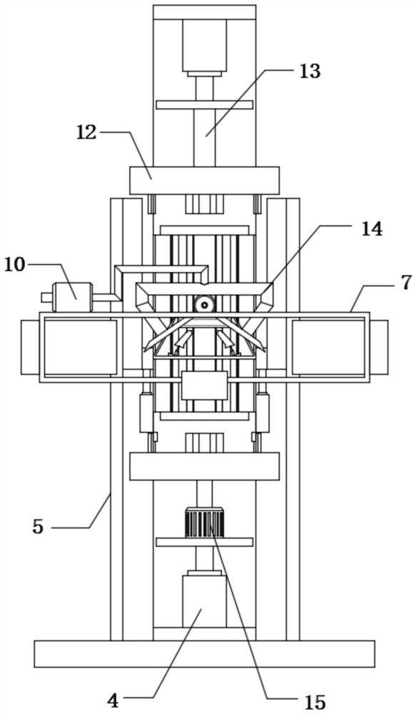
[0028] refer to Figure 1-3, an auxiliary device for enameled wire winding, including a base 1 and a winding roller 35, the top outer wall of the base 1 is fixedly connected with two fixed plates 5, and the outer walls of the opposite sides of the two fixed plates 5 are fixedly connected with guide rails 16, the two The inner walls of the guide rails 16 are all slidably connected with sliding blocks 18, the opposite side outer walls of the two sliding blocks 18 are fixedly connected with the same trapezoidal frame 17, and the outer walls of the two fixed plates 5 below the trapezoidal frame 17 are all fixedly connected with supports. plate 21, and the top outer walls...


PUM


Abstract

The invention belongs to the technical field of enameled wire production, and particularly relates to an auxiliary device for enameled wire winding. The auxiliary device is characterized in that the auxiliary device comprises a base and a winding roller, the outer wall of the top of the base is fixedly connected with two fixing plates, the outer walls of the opposite sides of the two fixing plates are fixedly connected with guide rails, and the inner walls of the two guide rails are slidably connected with sliding blocks. By arranging a first air cylinder, an extrusion plate, a limiting telescopic rod, an adaptive spring and a strip-shaped extrusion arc rod, when a motor drives a winding roller to conduct winding operation of an enameled wire, the first air cylinder is adjusted to drive the strip-shaped extrusion arc rod on the extrusion plate to make contact with the enameled wire, the adaptive spring drives the strip-shaped extrusion arc rod to extrude the enameled wire, so that all layers of the enameled wire are in perfect fit, the winding effect is improved, the adaptive spring drives the strip-shaped extrusion arc rod to extrude the enameled wire, so that the enameled wire is prevented from being damaged due to excessive extrusion, and the enameled wire is protected.

Description

technical field [0001] The invention relates to the technical field of enameled wire production, in particular to an auxiliary device for enameled wire winding. Background technique [0002] Enameled wire is a main variety of winding wire, which is composed of conductor and insulating layer. After the bare wire is annealed and softened, it is painted and baked many times. However, it is not easy to produce products that meet both standard requirements and customer requirements. It is affected by factors such as raw material quality, process parameters, production equipment, and the environment. Therefore, the quality characteristics of various enameled wires are different, but they all have Mechanical properties, chemical properties, electrical properties, thermal properties four major properties. [0003] When the existing enameled wire is produced, it needs to be wound on the winding roller. During the winding process, it needs to be assisted by an auxiliary device. Durin...

Claims


Application Information

Patent Timeline
IPC IPC(8): B65H54/553B65H54/44B65H71/00B65H54/70B65H59/10
CPCB65H54/553B65H54/44B65H71/00B65H54/702B65H59/10B65H2701/34
Inventor 袁亚亚钟学成苏保信赵俊王清华吕青王剑钊胡志康查超梁玉梅
Owner TONGLING JINGDA SPECIAL MAGNET WIRE CO LTD
Learn More