High-precision automatic feeding and cutting mechanism

An automatic feeding and high-precision technology, which is applied in the field of stamping strip processing, can solve the problems of increasing the strength of operators, time-consuming and laborious strip inspection, and poor human-computer interaction effects, etc., and achieves simple structure, low manufacturing cost, and mechanism action. The effect of simplification

Inactive Publication Date: 2021-12-31
昆山佳旺德自动化设备有限公司
View PDF0 Cites 0 Cited by
  • Summary
  • Abstract
  • Description
  • Claims
  • Application Information

AI Technical Summary

Problems solved by technology

[0004] The purpose of the present invention is to provide a high-precision automatic feeding and cutting mechanism to solve the problem that the above-mentioned existing technical mechanism is relatively large, the positioning accuracy is not accurate, the movement and the structure are unstable; the action sequence is long, the sound noise is relatively large, and the cutting The cutting burr is large; the human-computer interaction effect is poor, and the inspection of the material belt is time-consuming and laborious, which increases the strength of the operator and other problems raised in the background technology

Method used


Image

  • High-precision automatic feeding and cutting mechanism
  • High-precision automatic feeding and cutting mechanism
  • High-precision automatic feeding and cutting mechanism

Examples


Embodiment 1

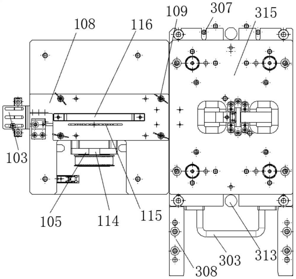
[0033] see Figure 1-10 , the present invention provides a technical solution: a high-precision automatic feeding and cutting mechanism, including a feeding assembly 100, a positioning assembly 200, and a cutting assembly 300, and the feeding assembly 100 and the cutting assembly 300 are connected through the positioning assembly 200 ;

[0034] The feed assembly 100 includes a first fixed plate 108, the top of the first fixed plate 108 is provided with a manual positioning mechanism 101, the bottom of the first fixed plate 108 is fixedly connected with a straight plate 110, and one side of the straight plate 110 is provided with a braking mechanism, the straight plate One side of 110 is rotatably connected with high-precision ratchet 104 through rotating shaft 114;

[0035] The positioning assembly 200 includes an automatic positioning module 201;

[0036] The cutting assembly 300 includes two baffle plates 302, an adjustable stroke cylinder 304 is arranged between the two b...

Embodiment 2

[0045] The same or corresponding components as those in Embodiment 1 use the corresponding reference numerals as in Embodiment 1, and for the sake of simplicity, only the differences from Embodiment 1 will be described below. The difference between this embodiment 2 and embodiment 1 is: the bottom of the second fixed plate 315 and the top of the moving plate 312 are all fixedly connected with a sleeve 313, the inside of the sleeve 313 is provided with a rectangular spring 306, and the top of the moving plate 312 The top is fixedly connected with several repeating positioning pins 307, and one side of the cutting die 310 is fixedly connected with a second handle 303; When installing, position the cutting die 310, push the spare die to the bottom and touch the repeat positioning pin 307, and then tighten the bolts to realize the rapid switching of the cutting die 310. After the auxiliary pressing belt knife, the standard The rectangular spring 306 acts in the sleeve 313, which c...

Embodiment 3

[0049] The same or corresponding components as those in Embodiment 2 use the corresponding reference numerals as in Embodiment 2. For the sake of simplicity, only the differences from Embodiment 2 will be described below. The difference between the embodiment 3 and the embodiment 2 is that: a tail detection probe 103 is provided on one side of the first fixing plate 108 . In the present invention, when each roll of material is used up, if the tailing detection probe 103 fails continuously, an alarm will be issued to remind the operator to replace the material tape roll in time, so as to provide more friendly human-computer interaction, remind the personnel when to change the material, and the butterfly The butterfly bolt 109 is easy to disassemble. Due to the risk of material being deformed and jammed, the butterfly bolt 109 needs to be quickly disassembled for the operator to troubleshoot. The accuracy of precise positioning in the separation from the stamping strip; the pres...


PUM


Abstract

The invention discloses a high-precision automatic feeding and cutting mechanism. The high-precision automatic feeding and cutting mechanism comprises a feeding assembly, a positioning assembly and a cutting assembly; the feeding assembly and the cutting assembly are connected through the positioning assembly; the feeding assembly comprises a first fixing plate; a manual positioning mechanism is arranged at the top of the first fixing plate; a tailing detection probe is arranged on one side of the first fixing plate; a straight plate is fixedly connected to the bottom of the first fixing plate; and a braking mechanism is arranged on one side of the straight plate. According to the high-precision automatic feeding and cutting mechanism, a servo motor drives a high-precision ratchet wheel to automatically feed a strip to a cutting die; the cutting die is used in cooperation with a high-precision guide column and a high-precision guide sleeve; the high-precision guide column and the high-precision guide sleeve are driven by a power source stroke-adjustable air cylinder; high-precision repeated blanking actions of an upper cutting knife and a lower cutting knife can be achieved; the stroke-adjustable air cylinder can walk in a small stroke after being adjusted; cutting power is provided at the same time; the stroke-adjustable air cylinder has buffering and limiting functions; noise can be effectively reduced; the action time is shortened; and the high-precision automatic feeding and cutting mechanism is simple in structure and high in precision.

Description

technical field [0001] The invention relates to the technical field of stamping strip processing, in particular to a high-precision automatic feeding and cutting mechanism. Background technique [0002] With the development of industry, automation equipment production has gradually increased the assembly accuracy and requirements of products, and vision such as CCD has gradually been widely used in the industry. In the current field, the assembly of products or vehicles tends to be miniaturized, precise, and diversified. The cutting of stamping strips requires fast action, easy operation, and low noise. More humane requirements have been put forward. Cutting can no longer meet production requirements. At present, most sheet metal stamping strip cutting mainly adopts: 1. Positioning through the punching hole of the strip; 2. Using the cylinder push-pull mechanism to realize the feeding of the strip; 3. Using a hard stop to limit the cutting stroke. [0003] There are many p...

Claims


Application Information

Patent Timeline
Patent Type & Authority Applications(China)
IPC IPC(8): B21D28/02B21D37/12B21D43/04B21D43/00B21C51/00
CPCB21D28/02B21D37/12B21D43/04B21D43/003B21C51/00
Inventor 孙森王永峰
Owner 昆山佳旺德自动化设备有限公司
Why Eureka
Try Eureka