
Soybean no-tillage ridging precision seeding technology and mechanical equipment

A kind of mechanical equipment and soybean technology, which is applied to agricultural machinery and implements, shovels, plows, etc., can solve the problems of reducing ridging quality, poor practicability, and increasing soil compactness, so as to improve ridging quality, improve shaping effect, and improve The effect of practicality

Inactive Publication Date: 2021-12-31
CANGZHOU ACAD OF AGRI & FORESTRY SCI
View PDF7 Cites 2 Cited by
  • Summary
  • Abstract
  • Description
  • Claims
  • Application Information

AI Technical Summary

Problems solved by technology

[0002] Before planting the land, it is necessary to make a ridge, insert the plow into the soil, use a machine to pull the plow in front, draw a furrow where the plow has passed, and draw the next ditch in parallel when turning around, and a line between the ditch and the ditch is formed. Ridges, when the ridge device is currently in use during the process of sowing soybeans, in the prior art CN201920788510.8, the device uses rollers to roll the upturned soil, and the rolled ground forms a ditch. Ridge, this kind of ridge tends to increase the compactness of the soil, which is not conducive to the rapid germination of seeds, and the shape of the ridge is poor, which reduces the quality of the ridge and is poor in practicability

Method used


Image

  • Soybean no-tillage ridging precision seeding technology and mechanical equipment
  • Soybean no-tillage ridging precision seeding technology and mechanical equipment
  • Soybean no-tillage ridging precision seeding technology and mechanical equipment

Examples


Embodiment 1

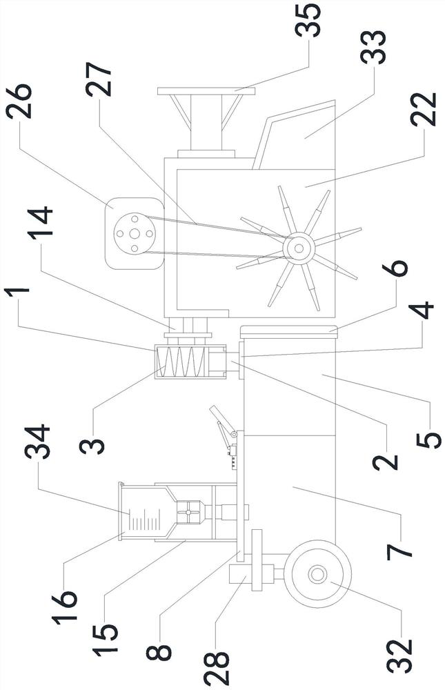
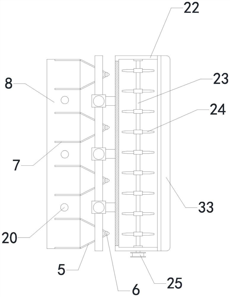
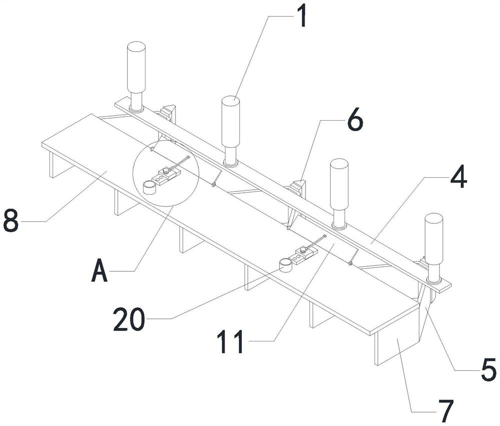
[0026]Multiple sets of first upper pillars 1 are installed on the outer sidewall of the soil breaking device through mounting brackets 14, the bottom ends of multiple sets of first upper pillars 1 are respectively provided with openings, and the tops of multiple sets of first lower pillars 2 are respectively slidably installed on multiple sets of first upper pillars 2. Inside the opening of the upper pillar 1, multiple groups of first springs 3 are installed in the openings of the multiple groups of the first upper pillar 1 respectively. The tops are all connected to the bottom ends of the connecting arms 4, and the shapes of the multi-group diverter plates 5 are all set in a "V" shape, and the multi-group headers 6 are respectively installed on the right end of the multi-group diverter plates 5, and the multi-group side plates 7 are respectively installed on the multi-group manifolds. The left end of the group flow plate 5, the bottom end of the top plate 8 are connected with ...

Embodiment 2

[0028] Multiple sets of first upper pillars 1 are installed on the outer sidewall of the soil breaking device through mounting brackets 14, the bottom ends of multiple sets of first upper pillars 1 are respectively provided with openings, and the tops of multiple sets of first lower pillars 2 are respectively slidably installed on multiple sets of first upper pillars 2. Inside the opening of the upper pillar 1, multiple groups of first springs 3 are installed in the openings of the multiple groups of the first upper pillar 1 respectively. The tops are all connected to the bottom ends of the connecting arms 4, and the shapes of the multi-group diverter plates 5 are all set in a "V" shape, and the multi-group headers 6 are respectively installed on the right end of the multi-group diverter plates 5, and the multi-group side plates 7 are respectively installed on the multi-group manifolds. The left end of the group flow plate 5, the bottom end of the top plate 8 are connected with...

Embodiment 3

[0030] A kind of soybean no-tillage ridge precise sowing technique comprises the following steps:

[0031] Step 1: Rotate the multiple sets of box lids 21 upward to open the feed ports at the top of the multiple sets of storage tanks 16, and place the soybean fertilizer inside the multiple sets of storage tanks 16 through the feed ports of the multiple sets of storage tanks 16;

[0032] Step 2: After the ridging device completes the soil ridging, multiple sets of first rotating shafts 18 are driven to rotate by turning on multiple sets of driving motors, and multiple sets of baffle plates 19 are used to transport the fertilizer downward after the multiple sets of first rotating shafts 18 rotate. Make the fertilizer fall to the top of the ridging soil through the connecting pipe 20, and at this time, the ridging operation is carried out during the continuous advancement of the equipment, so that the baffle plate 19 continuously transports the fertilizer;

[0033] Step 3: Soybea...


PUM


Abstract

The invention relates to the technical field of precision seeding technologies and mechanical equipment, in particular to a soybean no-tillage ridging precision seeding technology and mechanical equipment, and aims to improve the soil ridging quality, avoid soil compaction caused by soil extrusion and improve the practicability. The mechanical equipment comprises a ridging device, a seeding device, a soil crushing device and a supporting device, the ridging device is installed on the outer side wall of the soil crushing device, the soil crushing device is connected with an external traction mechanism, the seeding device is arranged at the top end of the ridging device, and the supporting device is installed on the outer side wall of the ridging device; and the ridging device comprises a first upper supporting column, a plurality of groups of first lower supporting columns, a plurality of groups of first springs, a connecting arm, a plurality of groups of splitter plates, a plurality of groups of top heads, a plurality of groups of side plates, a top plate, a plurality of groups of sliding rails, a plurality of groups of sliding blocks, a plurality of groups of inclined plates, a plurality of groups of supporting arms, a plurality of groups of bolts and a mounting frame, the plurality of groups of first upper supporting columns are installed on the outer side wall of the soil crushing device through an installation frame, and openings are formed in the bottom ends of the first upper supporting columns correspondingly.

Description

technical field [0001] The invention relates to the technical field of precision sowing technology and mechanical equipment, in particular to a no-tillage ridge precision sowing technology and mechanical equipment for soybeans. Background technique [0002] Before planting the land, it is necessary to make a ridge, insert the plow into the soil, use a machine to pull the plow in front, draw a furrow where the plow has passed, and draw the next ditch in parallel when turning around, and a line between the ditch and the ditch is formed. Ridges, when the ridge device is currently in use during the process of sowing soybeans, in the prior art CN201920788510.8, the device uses rollers to roll the upturned soil, and the rolled ground forms a ditch. Ridging, this way of ridges tends to increase the compactness of the soil, which is not conducive to the rapid germination of seeds, and the shape of the ridges is poor, which reduces the quality of the ridges and is poor in practicabil...

Claims


Application Information

Patent Timeline
Patent Type & Authority Applications(China)
IPC IPC(8): A01B49/06A01B13/02
CPCA01B49/06A01B13/02
Inventor 胡铁欢曹金锋孙永媛孙世军
Owner CANGZHOU ACAD OF AGRI & FORESTRY SCI
Learn More