
Magnetic block assembling device for outer rotor

A technology for assembling devices and outer rotors, which is applied to electromechanical devices, manufacturing stator/rotor bodies, magnetic circuits, etc., can solve problems such as poor flexibility, scratched magnetic blocks, crushed magnetic blocks, etc., and achieves the effect of convenient replacement.

Active Publication Date: 2021-12-28
杭州合慧智能装备有限公司
View PDF8 Cites 0 Cited by
  • Summary
  • Abstract
  • Description
  • Claims
  • Application Information

AI Technical Summary

Problems solved by technology

[0002] The magnetic block assembly method of the existing rotor is as follows: the inner wall of the rotor casing is coated with glue, and the magnetic block knife is pressed against the inner wall of the rotor casing to push the magnetic block from the outside to the inside. This pushing process will easily cause the glue to be scooped out of the casing. Scratch the magnetic block, or even crush the magnetic block, the flexibility is poor, generally only a specific outer rotor can be assembled

Method used


Image

  • Magnetic block assembling device for outer rotor
  • Magnetic block assembling device for outer rotor
  • Magnetic block assembling device for outer rotor

Examples


Embodiment Construction

[0036] The present invention will be further described below in conjunction with the accompanying drawings and specific implementation.

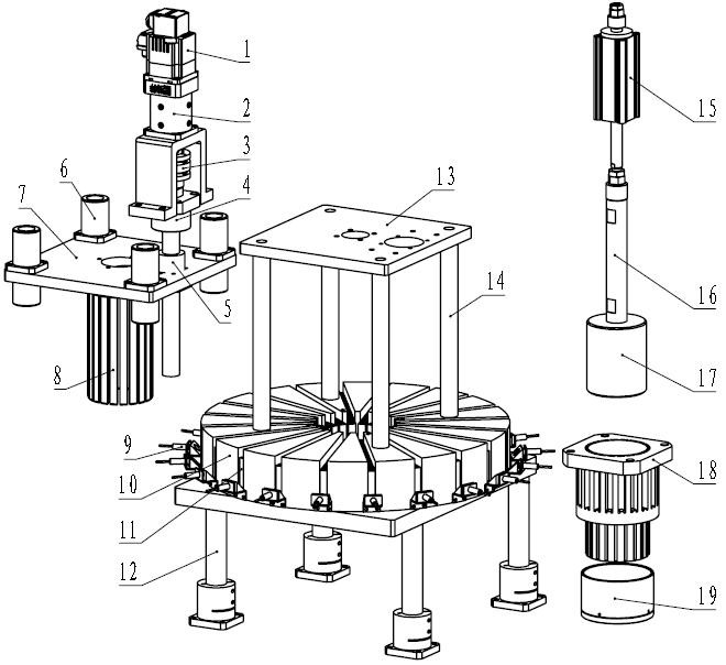
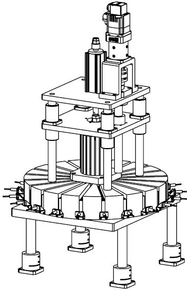
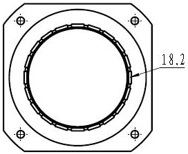
[0037] Such as figure 1 and figure 2 As shown, four columns 12 support a mounting plate, and a circular magnetic block material tray 10 is arranged on the mounting plate. A through hole is provided in the center of the magnetic block material plate 10 and a magnetic block guide seat 18 is arranged. A plurality of rectangular through slots arranged radially are arranged in the cloth, and a magnetic block 11 is housed in the rectangular through slots.

[0038] In a specific implementation, a plurality of magnetic blocks 11 are installed in the rectangular slot of the magnetic block guide seat 18 , and the plurality of magnetic blocks 11 are magnetically attracted and tightly stacked along the radial direction of the magnetic block guide seat 18 .

[0039] Such as Figure 3 to Figure 5 As shown, the inner part of the upper part of the magne...


PUM


Abstract

The invention discloses a magnetic block assembling device for an outer rotor. A plurality of radial rectangular through grooves are evenly formed in the magnetic block material disc in the circumferential direction, the magnetic blocks are installed in the rectangular through grooves of a magnetic block guide seat, the magnetic block guide seat is arranged on the magnetic block material disc, a center through hole is formed in the center of the magnetic block guide seat, a sliding groove structure is arranged in the upper portion of the magnetic block guide seat, the sliding groove structure comprises a vertical sliding groove close to the center through hole and a horizontal sliding groove in the outer side. A central magnet is sleeved in a center through hole of the magnetic block guide seat and magnetically attracts a magnetic block, a rotor shell sleeves the lower part of the magnetic block guide seat, and an annular gap is formed between the rotor shell and the magnetic block guide seat; a magnetic block cutter is arranged over a magnetic block guide seat, and the magnetic block cutter extends into a vertical sliding groove of the magnetic block guide seat to press a magnetic block downwards. According to the invention, the stacked magnetic blocks can be quickly assembled in the rotor shell one by one, relative friction between the magnetic blocks and the shell is avoided in the assembly process, glue is effectively prevented from being pushed out, the magnetic blocks are effectively prevented from being scratched, and the model change is convenient.

Description

technical field [0001] The invention relates to a magnetic block assembly device, in particular to a magnetic block assembly device for an outer rotor. Background technique [0002] The magnetic block assembly method of the existing rotor is as follows: the inner wall of the rotor casing is coated with glue, and the magnetic block knife is pressed against the inner wall of the rotor casing to push the magnetic block from the outside to the inside. This pushing process will easily cause the glue to be scooped out of the casing. Scratching or even crushing the magnetic block has poor flexibility, and generally only a specific outer rotor can be assembled. Contents of the invention [0003] In order to solve the problems in the background technology, the present invention proposes a magnetic block assembly device for an outer rotor. [0004] Technical scheme of the present invention is: [0005] It includes a magnetic block material tray, on which a magnetic block guide sea...

Claims


Application Information

Patent Timeline
Patent Type & Authority Applications(China)
IPC IPC(8): H02K15/03H02K1/27
CPCH02K15/03H02K1/2786
Inventor 谢轩武振宇楼周侃余桢慧蔡有成沈红兵赵松文顾哲伟
Owner 杭州合慧智能装备有限公司
Learn More