
Rail transit power supply system based on three-phase inverter power supply device

A technology of power supply device and three-phase inverter, which is applied in the direction of circuit devices, DC network circuit devices, power lines, etc., can solve the problems of mismatching power supply capacity, top-heavy, and increasing number of external power supply equipment, and achieve the reduction of medium-voltage equipment Quantity, the effect of reducing the amount of work

Pending Publication Date: 2021-12-28
CHINA RAILWAY ERYUAN ENG GRP CO LTD
View PDF0 Cites 0 Cited by
  • Summary
  • Abstract
  • Description
  • Claims
  • Application Information

AI Technical Summary

Problems solved by technology

[0007] For this kind of rail transit project with light power supply load, in order to meet the power supply demand of this part of the primary load with small power, if the design is still carried out according to the conventional power supply system scheme, the medium-voltage power supply network with double ring network is adopted, and the substation adopts single The scheme of bus segment and dual distribution transformers, providing two independent power supplies will not only lead to complex configuration schemes for external input power matching, medium voltage power supply ring network system and substations, but also external power supply, medium voltage ring network cables and The number of equipment has increased significantly, and at the same time, the area occupied by each substation and the project investment have increased significantly, which is not in line with the original intention of the construction of this type of rail transit project, which requires low project investment and small footprint
At the same time, due to the relatively small demand for traction power supply at the load terminal and low-voltage dynamic lighting load power supply, if the conventional scheme is still implemented, the entire power supply system scheme will appear top-heavy, and the power supply capacity will not match up and down. Serious waste of engineering investment

Method used


Image

  • Rail transit power supply system based on three-phase inverter power supply device
  • Rail transit power supply system based on three-phase inverter power supply device

Examples


Embodiment Construction

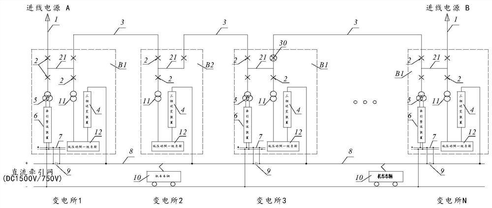
[0024] A rail transit power supply system scheme based on a three-phase inverter power supply device proposed by the present invention will be further described below in conjunction with the accompanying drawings.

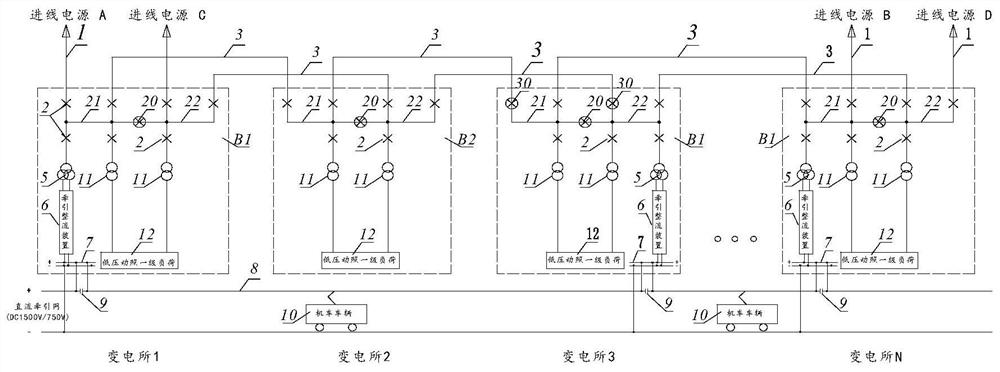
[0025] The conventional power supply system scheme of the rail transit project adopts the medium-voltage power supply network of the double ring network, and the substation adopts the scheme of single busbar segmentation and double distribution transformers. The following takes a typical power supply scheme that introduces 4 circuits of external incoming power from the local power grid as an example for comparison and description.

[0026] refer to figure 1 , the conventional power supply system scheme introduces 4 external incoming power sources 1 from the local power grid, and supplies power to several traction step-down hybrid substations B1 and step-down substations B2 along the project through two medium-voltage power supply ring networks 3 . The external inc...


PUM


Abstract

The invention discloses a rail transit power supply system based on a three-phase inverter power supply device, and aims to effectively simplify the whole power supply system scheme, reduce the number of medium-voltage ring network cables and equipment, and greatly reduce the construction scale of each substation and the engineering investment of the whole power supply system. The rail transit power supply system comprises a traction power supply system and a low-voltage power supply and distribution system, two external incoming line power supplies are introduced from a local power grid, power is supplied to a plurality of traction and voltage reduction hybrid substations and voltage reduction substations along a project through a medium-voltage power supply looped network, the two external incoming line power supplies are respectively introduced into a substation medium-voltage I-section bus through substation medium-voltage switches, and the medium-voltage power supply looped network is connected with the substation medium-voltage I-section bus of the traction and voltage reduction hybrid substation and a voltage reduction substation along a project through a substation medium-voltage switch.

Description

technical field [0001] The patent of the present invention relates to rail transit engineering, in particular to a rail transit power supply system based on a three-phase inverter power supply device, through the cooperative application of traction rectifier units, DC traction networks, distribution transformers and three-phase inverter power supply devices Rail transit engineering traction and low-voltage distribution power supply. Background technique [0002] At present, the traction power supply system of most urban rail transit projects adopts the traction power supply system of DC1500V (or DC750V) catenary (or contact rail) current delivery and running rail return. [0003] According to the calculation of traction power supply, traction substations are set up in some stations, which are integrated with the step-down substations at the same site to form traction step-down substations, and only step-down substations are set in some stations. The traction rectifier unit ...

Claims


Application Information

Patent Timeline
IPC IPC(8): H02J1/00H02J1/06H02J3/00H02J4/00B60M3/00
CPCH02J4/00H02J1/00H02J3/00H02J3/0073H02J1/06B60M3/00
Inventor 张开波江安聂飞周才发刘卫东曾之煜陈桁向往
Owner CHINA RAILWAY ERYUAN ENG GRP CO LTD
Learn More