


Quick Research
Generate reliable direction feasibility study reports for your R&D in just a few steps.

Technical Q&A
Discover and master advanced knowledge NOW. Basics, ideas, possibilities, all at once.

Find Solutions
As an expert in R&D theories, this can generate solutions to your technical problems instantly.

Evaluate Feasibility
Analyze your overall solution with one click, know your potential R&D risks in advance.

Monitor Landscape
Get weekly tech updates, stay abreast of the latest tech innovations and key insights.
Yarn winding machine capable of quantifying yarn and using method of yarn winding machine
A winding machine and yarn technology, which is applied in the field of yarn winding, can solve the problems of manual cutting error, inconvenient automatic cutting of yarn, and inability to replace the winding column in time, so as to achieve high cutting efficiency and improve efficiency Effect
- Summary
- Abstract
- Description
- Claims
- Application Information
AI Technical Summary
Problems solved by technology
Method used
Image


Examples
Embodiment 1
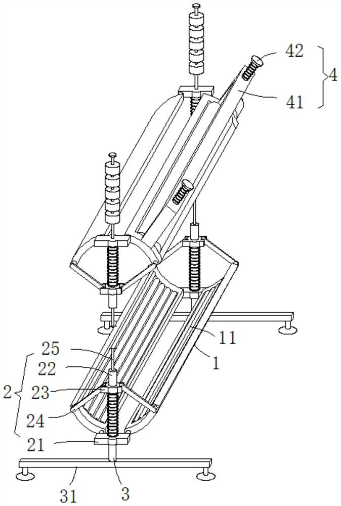
[0037] see figure 1 , figure 2 and Figure 5 , this embodiment provides a yarn winding machine that can perform quantitative yarn and its use method, including two supporting mechanisms 2, four arc-shaped clamping plates 1 and a conveying mechanism 5, and the four arc-shaped clamping plates 1 are divided into Two groups, two are a group and are symmetrically distributed left and right, two sets of arc-shaped splints 1 are symmetrically distributed up and down, two supporting mechanisms 2 are located on the front and rear sides of the arc-shaped splint 1, respectively, and the four arc-shaped splints 1 constitute a rolling clamp. The space of the winding roller changes the traditional use of a fixed rolling support to roll and support the yarn winding roller. The traditional support cannot adapt to the size of the rolling egg support space according to the winding volume of the winding roller. Therefore, the winding roller winds the yarn. The phenomenon of loosening is easy ...
Embodiment 2
[0049] see figure 1 , image 3 and Figure 4 , made further improvements on the basis of Example 1:
[0050] The transmission mechanism 5 also includes a driven roller 53. Compensation grooves 12 are provided on both side walls of the installation hole of the arc-shaped splint 1. The compensation groove 12 is provided with a reinforcing rod 13, and the outer wall of the reinforcing rod 13 is slidably sleeved with a sliding sleeve. The cylinder 14, the radial side wall of the sliding sleeve 14 is rotatably provided with a pin shaft that is rotatably connected to the shaft end of the driven roller 53, and the driven roller 53 is rotatably connected to the two sliding sleeves 14 through the pin shaft, while the sliding sleeve 14 can slide along the outer wall of the reinforcing rod 13 along the driven roller 53, so that the driven roller 53 and the driving roller 52 can roll and fit together in real time, and the yarn to be wound is wound around the upper side of the outer wall...
Embodiment 3
[0053] see Figure 1-2 , made further improvements on the basis of Example 2:
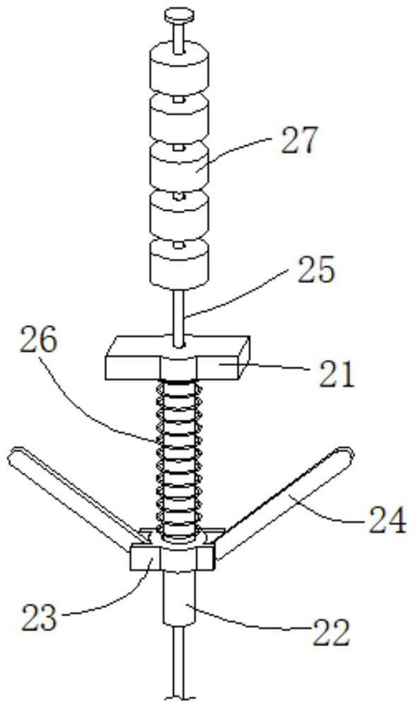
[0054] The outer wall of the sliding rod 22 is slidably sleeved with a first spring 26 located between the connecting seat 21 and the sliding seat 23, and the elastic potential energy of the first spring 26 is used to push the sliding seat 23 to the side of the power transport connecting seat 21 in real time. , so that the arc-shaped splint 1 can be rotated around one end of the connecting seat 21 by the hinge rod 24, so that the arc-shaped splint 1 can be attached to the outer wall of the winding roller in real time, so as to prevent the winding roller from separating from the upper and lower sets of the arc-shaped splint 1. Rolling clamping gap.
[0055] The outer wall of the guide rod 25 is slidably sleeved with a number of counterweight discs 27 located at the upper end of the upper connecting seat 21. The top of the guide rod 25 is fixedly provided with a limit block to prevent the counterwei...
PUM
 Abstract
Description
Claims
Application Information
 - R&D Engineer
- R&D Manager
- IP Professional
- Industry Leading Data Capabilities
- Powerful AI technology
- Patent DNA Extraction
Browse by: Latest US Patents, China's latest patents, Technical Efficacy Thesaurus, Application Domain, Technology Topic, Popular Technical Reports.
© 2024 PatSnap. All rights reserved.Legal|Privacy policy|Modern Slavery Act Transparency Statement|Sitemap|About US| Contact US: help@patsnap.com