Hydraulic cylinder machining cutting equipment capable of fixing piston rods with different diameters

A technology of cutting equipment and piston rod, which is applied in the field of hydraulic cylinder processing, can solve the problems of limited application range, inconvenient automatic cleaning of support table debris, inconvenient fixing of piston rods with different diameters, etc., and achieves the effect of convenient positioning operation

Inactive Publication Date: 2021-12-28
徐州山恒机械制造有限公司
View PDF0 Cites 1 Cited by
  • Summary
  • Abstract
  • Description
  • Claims
  • Application Information

AI Technical Summary

Problems solved by technology

[0003] The purpose of the present invention is to provide a hydraulic cylinder processing cutting equipment that can fix piston rods of different diameters, to solve the problem that the existing cutting equipment proposed in the background technology is inconvenient to fix piston rods of different diameters, and the scope of use is relatively limited. The problem that it is inconvenient to automatically clean up the debris on the support table after the cutting of the rod

Method used


Image

  • Hydraulic cylinder machining cutting equipment capable of fixing piston rods with different diameters
  • Hydraulic cylinder machining cutting equipment capable of fixing piston rods with different diameters
  • Hydraulic cylinder machining cutting equipment capable of fixing piston rods with different diameters

Examples


Embodiment Construction

[0037] The following will clearly and completely describe the technical solutions in the embodiments of the present invention with reference to the accompanying drawings in the embodiments of the present invention. Obviously, the described embodiments are only some, not all, embodiments of the present invention. Based on the embodiments of the present invention, all other embodiments obtained by persons of ordinary skill in the art without making creative efforts belong to the protection scope of the present invention.

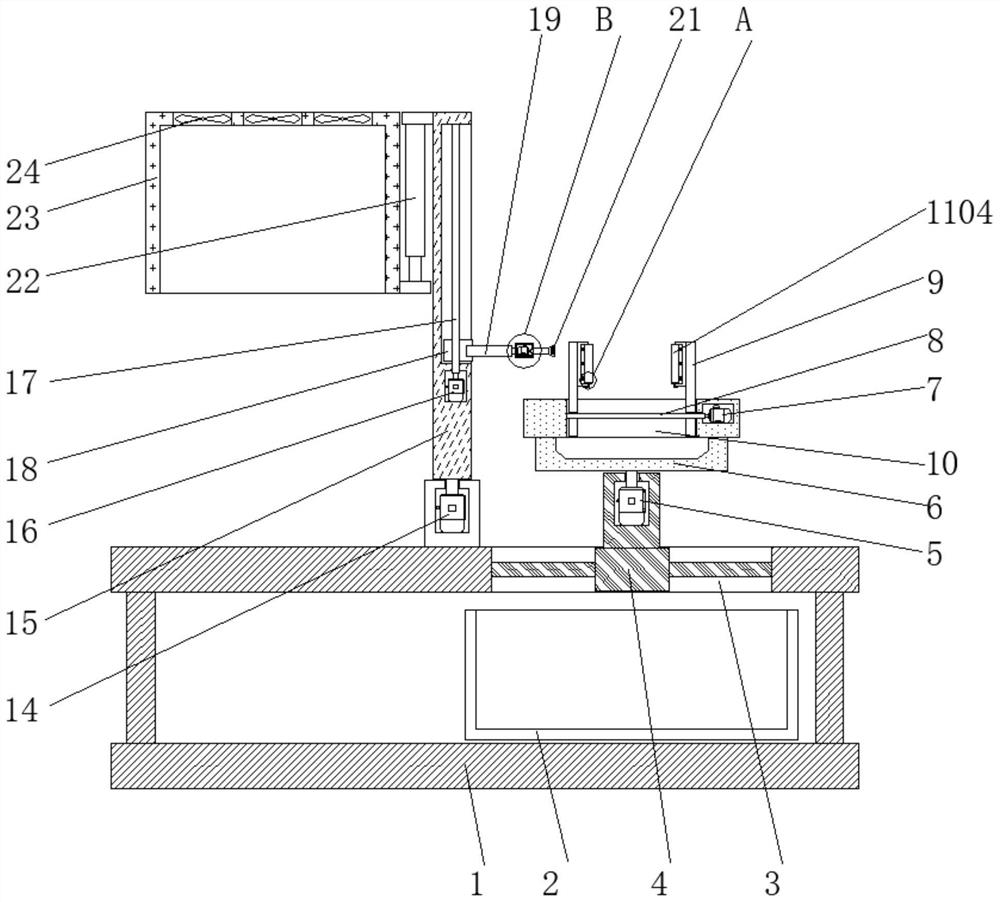
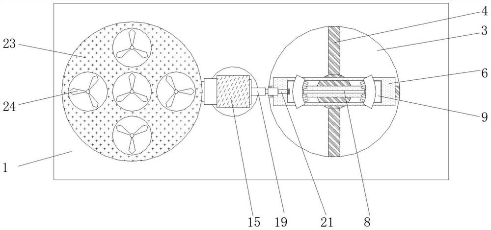
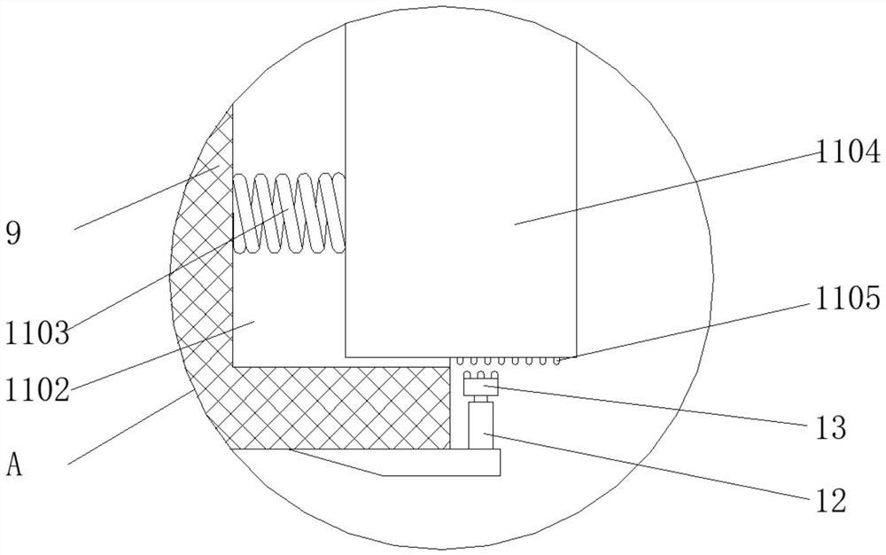
[0038] see Figure 1-6 , the present invention provides a technical solution: a cutting device for hydraulic cylinder processing that can fix piston rods of different diameters, according to figure 1 and figure 2 As shown, a collection box 2 is placed on the inner bottom of the carrying platform 1, and an opening 3 is provided on the upper side of the collecting box 2, and the opening 3 is opened on the top of the carrying platform 1 at the same time, and a ...


PUM


Abstract

The invention discloses hydraulic cylinder machining cutting equipment capable of fixing piston rods with different diameters. The hydraulic cylinder machining cutting equipment comprises a bearing table, a clamping mechanism, a first electric telescopic column, a third motor, a rotating frame and a fifth motor, a collecting box is placed at the inner bottom of the bearing table, a support is fixed in an opening, the clamping mechanism is fixed to the inner end faces of clamping plates, the rotating frame is rotationally connected to the top of the bearing table, one side of a sliding block is connected with the fifth motor through an electric telescopic rod, a second electric telescopic column is fixed to the other end face of the rotating frame, and the bottom of the second electric telescopic column is connected with a blocking cover. According to the hydraulic cylinder machining cutting equipment capable of fixing the piston rods with different diameters, and after the piston rods are vertically placed between the two clamping plates, the two clamping plates get close to each other, the piston rods are conveniently clamped and fixed, at the moment, compression springs play a role in jacking and supporting movable clamping blocks, all the movable clamping blocks are abutted against the piston rods, and therefore the piston rods with different diameters can be clamped and fixed by matching with fixed clamping blocks.

Description

technical field [0001] The invention relates to the related technical field of hydraulic cylinder processing, in particular to a cutting device for processing hydraulic cylinders capable of fixing piston rods with different diameters. Background technique [0002] The hydraulic cylinder is a hydraulic actuator that converts hydraulic energy into mechanical energy and performs linear reciprocating motion. It has a simple structure and reliable operation. When it is used to realize reciprocating motion, the deceleration device can be eliminated, and there is no transmission gap, and the motion is stable. Therefore It is widely used in various mechanical hydraulic systems. Cutting equipment is required when cutting the piston rod on the hydraulic cylinder. The existing cutting equipment is inconvenient to fix piston rods of different diameters, and the scope of use is relatively limited. Complete the piston It is inconvenient to automatically clean up the debris on the support ...

Claims


Application Information

Patent Timeline
Patent Type & Authority Applications(China)
IPC IPC(8): B23Q3/06B23Q1/26B23Q11/00B23Q5/10B23Q5/28B23C3/00
CPCB23Q3/06B23Q1/26B23Q11/005B23Q5/10B23Q5/28B23C3/00
Inventor 张巍然
Owner 徐州山恒机械制造有限公司
Why Eureka
Try Eureka