
Portal frame type arch frame transportation structure, tunnel construction device and construction method

A tunnel construction and gantry-type technology, which is applied in transportation and packaging, tunnels, tunnel linings, etc., can solve the problems of prolonging the tunnel construction time, not being suitable for tunnels with small widths, difficulties, etc., and achieve the effect of saving construction time

Pending Publication Date: 2021-12-24
SICHUAN LANHAI ENG EQUIP MFG CO LTD
View PDF0 Cites 0 Cited by
  • Summary
  • Abstract
  • Description
  • Claims
  • Application Information

AI Technical Summary

Problems solved by technology

[0002] In tunnel construction, multiple processes are usually involved, such as erecting, rock drilling, spraying, etc. For tunnels with a small width (the width of the opening is less than 6m), it is necessary to drive into a fully functional engineering trolley. It is relatively difficult to say, because the engineering trolley is large, other vehicles cannot enter after entering the tunnel, and the working space of the engineering trolley is limited, so it is not suitable for construction in a tunnel with a small width
[0003] Before tunnel construction, the usual construction steps are to transport the arch frame to be erected into the tunnel by engineering vehicles, and then after the engineering vehicles exit the tunnel, the tunnel construction vehicles drive in to carry out the erection construction. In this way, the engineering vehicles need Frequent entry and exit will prolong the tunnel construction time, which is not conducive to the rapid progress of tunnel construction

Method used


Image

  • Portal frame type arch frame transportation structure, tunnel construction device and construction method
  • Portal frame type arch frame transportation structure, tunnel construction device and construction method
  • Portal frame type arch frame transportation structure, tunnel construction device and construction method

Examples


Embodiment 1

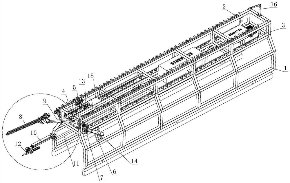
[0032] Such as Figure 1-3 As shown, a gantry-type arch transportation structure includes a gantry 1, the width of which is equivalent to the width of the tunnel, and is placed in the tunnel. The upper end of the gantry 1 is provided with a conveyor belt 3, and the conveyor belt 3 consists of Driven by the motor, the conveyor belt 3 can also be driven by a hydraulic motor to rotate relative to the door frame 1. The rotation direction of the conveyor belt 3 is from the outside of the tunnel to the inside of the tunnel, so that the arch frame is gradually transported forward. A plurality of arch support seats 2 are fixedly connected, and an arch can be placed on each arch support seat 2, and the two conveyor belts 3 are arranged symmetrically on both sides of the door frame 1, thereby ensuring the stability of the arch transportation. There is a one-to-one correspondence between the arch support seats 2 on the conveyor belt 3 . It can be understood that the arches are directly ...

Embodiment 2

[0035] A gantry type tunnel construction device, which can be directly placed in the tunnel for use during tunnel construction. With the continuous forward construction of the tunnel, the device can also be provided with a walking mechanism under it. The walking mechanism can be a crawler belt. The device can move forward continuously with the construction of the tunnel, thereby ensuring the progress of the construction.

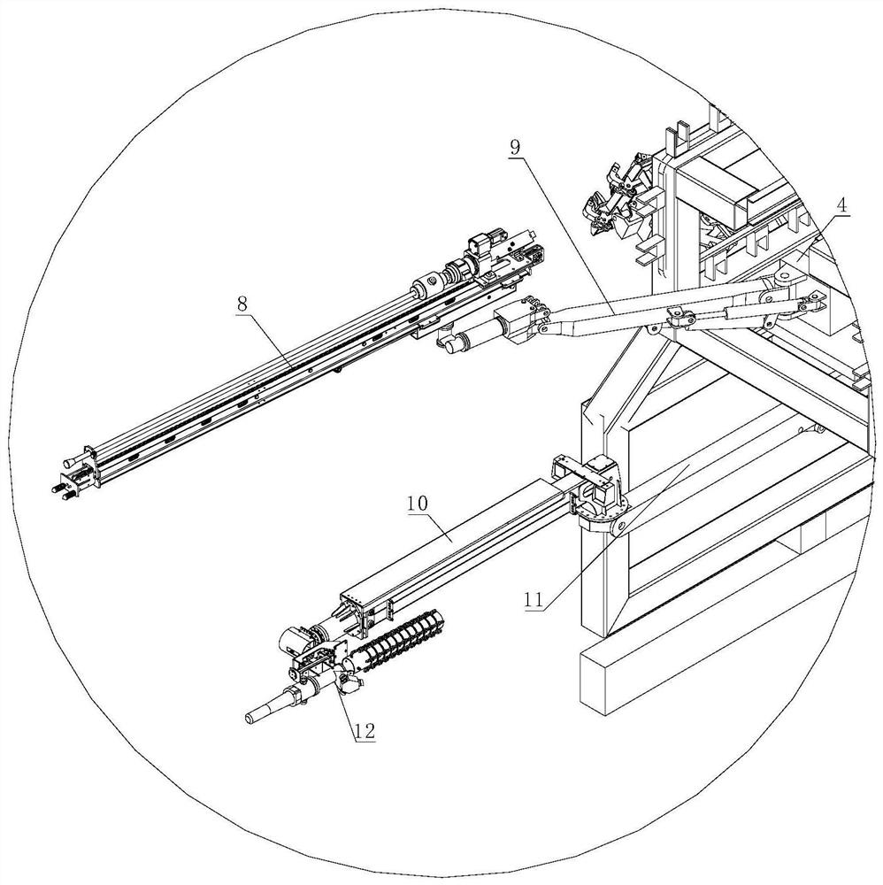
[0036] It specifically includes the above-mentioned gantry-type arch transport structure. A first moving part 15 is arranged on the upper part of the gantry 1. The first moving part 15 can be arranged on the axis of the gantry 1. The first moving part 15 is opposite to the door frame. 1 to move, the first manipulator 5 is set on the first moving part 15, the first manipulator 5 can grab the arch, the first manipulator 5 is hinged on the first moving part 15 through the first mechanical arm 13, the The first manipulator 13 is pitchable and telescopic, thereby...

Embodiment 3

[0044] The difference from the above-mentioned embodiment is that, if Figure 4-6 As shown, in this embodiment, an excavating device 17 is arranged in the portal frame 1, and the excavating device 17 is used to excavate the tunnel wall. There are methods, such as riveting, threaded connection, etc., when the excavating device 17 is not needed, the excavating device 17 can be removed; the excavating device 17 is provided with a transport device below, and the transport device is used to transport the excavated debris in the tunnel. Stones, debris, etc., are transported to the outside of the tunnel through the transport device.

[0045] The height of the rock drilling device 8 and the spraying arm 10 is lower than the height of the conveyor belt 3; the excavating device 17 is a roadheader.

[0046] The transportation device includes a conveyor belt 18, the length of which is equivalent to that of the door frame 1, and transports the excavated debris out of the tunnel; The slag...


PUM


Abstract

The invention relates to the technical field of tunnel construction equipment, in particular to a portal frame type arch frame transportation structure, a tunnel construction device and a construction method. The portal frame type tunnel construction device comprises the portal frame type arch frame transportation structure, a first moving part is arranged on the upper portion of a portal frame, a first manipulator is arranged on the first moving part, the first manipulator is hinged to the first moving part through a first mechanical arm, and the first mechanical arm can pitch and stretch out and draw back; and second manipulators are arranged on the two sides of the door frame and hinged to a second moving part through second mechanical arms, and the second mechanical arms can pitch and stretch out and draw back. According to the portal frame type tunnel construction device, an arch frame to be erected can be directly placed on a conveying structure and conveyed into a tunnel through movement of a conveying belt, then construction in the tunnel is completed through the manipulator, a rock drilling device and a guniting device on the portal frame, the device is small and exquisite in structure, engineering vehicles do not need to enter and exit frequently, and construction time is saved.

Description

technical field [0001] The invention belongs to the technical field of tunnel construction equipment, and in particular relates to a portal-type arch transport structure, a tunnel construction device and a construction method. Background technique [0002] In tunnel construction, multiple processes are usually involved, such as erecting, rock drilling, spraying, etc. For tunnels with a small width (the width of the opening is less than 6m), it is necessary to drive into a fully functional engineering trolley. It is relatively difficult to say, because the engineering trolley is large, other vehicles cannot enter after entering the tunnel, and the working space of the engineering trolley is limited, so it is not suitable for construction in a tunnel with a small width. [0003] Before tunnel construction, the usual construction steps are to transport the arch frame to be erected into the tunnel by engineering vehicles, and then after the engineering vehicles exit the tunnel, ...

Claims


Application Information

Patent Timeline
Patent Type & Authority Applications(China)
IPC IPC(8): E21D9/00E21D9/12E21D11/40E21F13/00E21D20/00E21D11/10
CPCE21D9/00E21D9/122E21D9/126E21D11/40E21F13/006E21D20/003E21D11/105
Inventor 兰冰冯怀何晓江邱章令
Owner SICHUAN LANHAI ENG EQUIP MFG CO LTD
Learn More