Flat field correction calibration method, device and system, computer equipment and medium

A flat field correction and calibration method technology, applied in the field of optical detection, can solve the problems of uneven brightness, adverse effects of measurement, and difficulty in accurate restoration of brightness, and achieve the effect of improving accuracy

Active Publication Date: 2021-12-21
华兴源创(成都)科技有限公司
View PDF7 Cites 0 Cited by
  • Summary
  • Abstract
  • Description
  • Claims
  • Application Information

AI Technical Summary

Problems solved by technology

[0003] The design of the lens itself is composed of a convex mirror, which will inevitably produce a bright center area in the imaging, and the brightness will show a linear attenuation to the edge area of ​​the lens. Therefore, this design will cause fatal brightness in optical automatic detection, which is difficult to accurately restore. , for a target with uniform brightness, an image with uneven brightness may be output, and the center brightness will always be higher than the edge brightness in optical photography, which will have an adverse effect on the subsequent target feature extraction, that is, measurement

Method used


Image

  • Flat field correction calibration method, device and system, computer equipment and medium
  • Flat field correction calibration method, device and system, computer equipment and medium
  • Flat field correction calibration method, device and system, computer equipment and medium

Examples


Embodiment Construction

[0041] In order to illustrate the present invention more clearly, the present invention will be further described below in conjunction with preferred embodiments and accompanying drawings. Similar parts in the figures are denoted by the same reference numerals. Those skilled in the art should understand that the content specifically described below is illustrative rather than restrictive, and should not limit the protection scope of the present invention.

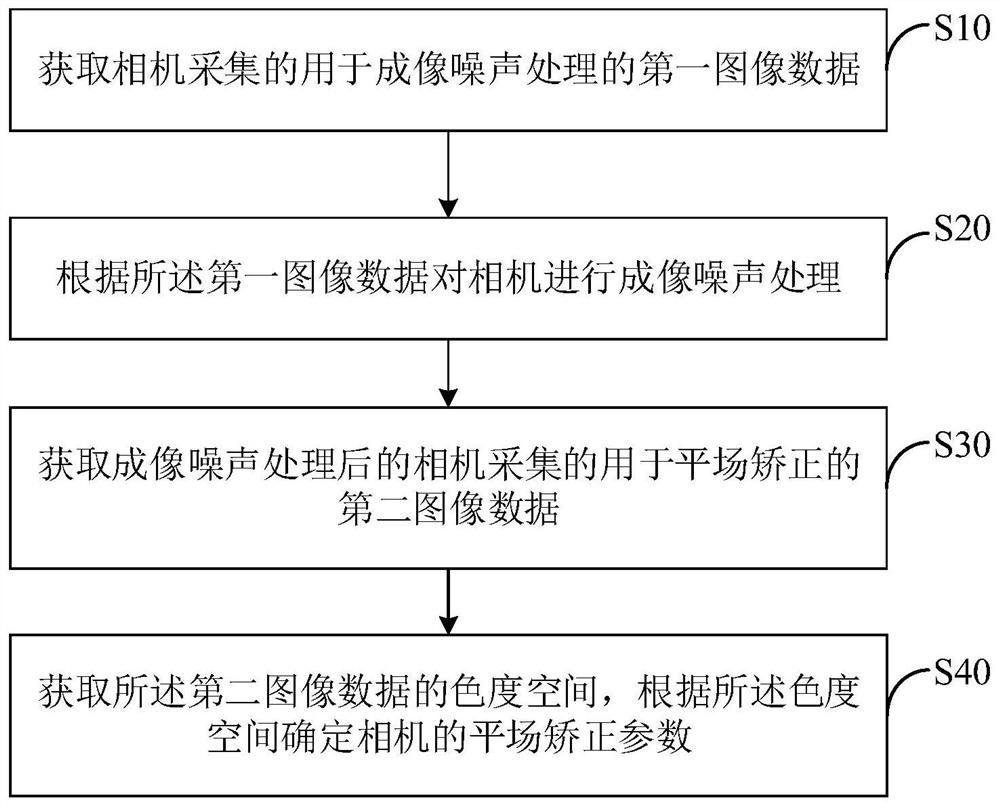
[0042] The first embodiment of the present invention proposes a camera flat-field correction calibration method, such as figure 1 As shown, the method includes:

[0043] S10: Acquire the first image data collected by the camera and used for imaging noise processing;

[0044] S20: Perform imaging noise processing on the camera according to the first image data;

[0045] S30: Acquire the second image data collected by the camera after imaging noise processing and used for flat-field correction;

[0046] S40: Acquire a chr...


PUM


Abstract

The invention discloses a flat field correction calibration method, device and system for a camera, computer equipment and a medium. The calibration method comprises the following steps: acquiring first image data which is acquired by the camera and is used for processing imaging noise; performing imaging noise processing on a camera according to the first image data; acquiring second image data used for flat field correction and acquired by the camera after imaging noise processing; and obtaining a chromaticity space of the second image data, and determining a flat field correction parameter of the camera according to the chromaticity space. The camera is corrected based on the flat field correction parameter, the corrected camera can accurately restore the brightness information of the shooting target, the problem that the center of a convex mirror lens is bright and the edge is dark is solved, and the accuracy of optical detection is improved.

Description

technical field [0001] The present invention relates to the field of optical detection, and more specifically, to a camera flat-field correction calibration method, device and system, computer equipment and media. Background technique [0002] The performance of machine vision mainly depends on the lens, light source, and camera in the system optics. It has high requirements for optical inspection, and light field correction is required when it is applied to customer scenarios. [0003] The design of the lens itself is composed of a convex mirror, which will inevitably produce a bright center area in the imaging, and the brightness will show a linear attenuation to the edge area of ​​the lens. Therefore, this design will cause fatal brightness in optical automatic detection, which is difficult to accurately restore. , for a target with uniform brightness, an image with uneven brightness may be output, and the center brightness will always be higher than the edge brightness i...

Claims


Application Information

Patent Timeline
Patent Type & Authority Applications(China)
IPC IPC(8): G06T7/80
CPCG06T7/80G06T2207/10024G06T2207/10052G06T2207/10152
Inventor 孙培
Owner 华兴源创(成都)科技有限公司
Why Eureka
Try Eureka