Optomechatronic integrated operation clamp device

A technology for operating clips and opto-mechanical devices, which is applied in the direction of workpiece clamping devices and manufacturing tools, can solve problems such as equipment smashing, objects falling, and fixtures that cannot be clamped easily, and achieve automatic control, automatic control, The effect of ensuring the safety of operation

Inactive Publication Date: 2021-12-21
陈斌
View PDF0 Cites 0 Cited by
  • Summary
  • Abstract
  • Description
  • Claims
  • Application Information

AI Technical Summary

Problems solved by technology

[0006] Aiming at the deficiencies of the prior art, the present invention provides an optical-mechanical-electrical-integrated operating fixture device, which has the advantages of realizing automatic control, effectively absorbing objects, effectively preventing objects from falling during transportation, ensuring the accuracy of equipment transportation, and solving the problem. The equipment fixture is easy to fail to hold, causing the object to fall and causing the equipment to be smashed

Method used


Image

  • Optomechatronic integrated operation clamp device
  • Optomechatronic integrated operation clamp device
  • Optomechatronic integrated operation clamp device

Examples


Embodiment 1

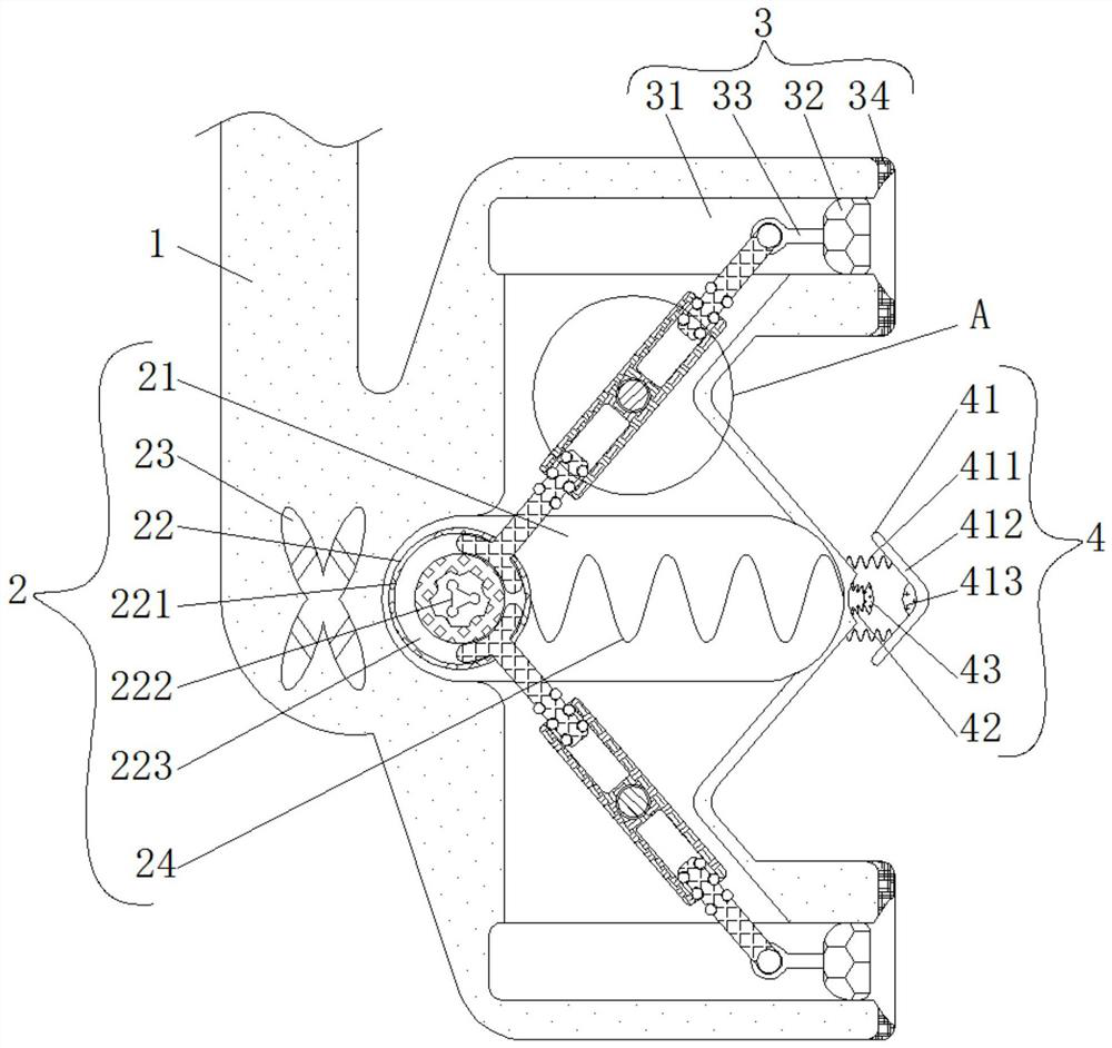
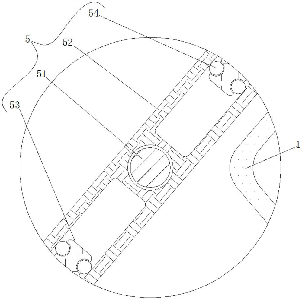
[0026] see figure 1 with image 3 , an optical-mechanical-electrical-integrated operating fixture device, including a clamping member 1, a transmission mechanism 2, an air pumping mechanism 3, a trigger mechanism 4, and a rotating mechanism 5, and the transmission mechanism 2 is elastically connected to the inside of the clamping member 1 and used to push The rotating mechanism 5 rotates and works, and the transmission mechanism 2 includes a movable groove 21, a stopper 22, an electromagnet 23 and a spring 24. The movable groove 21 is opened inside the clamping part 1, and the inside of the movable groove 21 is movably connected with a limiter 22. , the limiter 22 includes a moving part 221, a magnetic block 222 and an annular groove 223, the right side of the moving part 221 is fixedly connected with the spring one 24, the shape of the moving part 221 is a sphere and the material of the moving part 221 is a hard high-strength material , the moving part 221 plays the role of ...

Embodiment 2

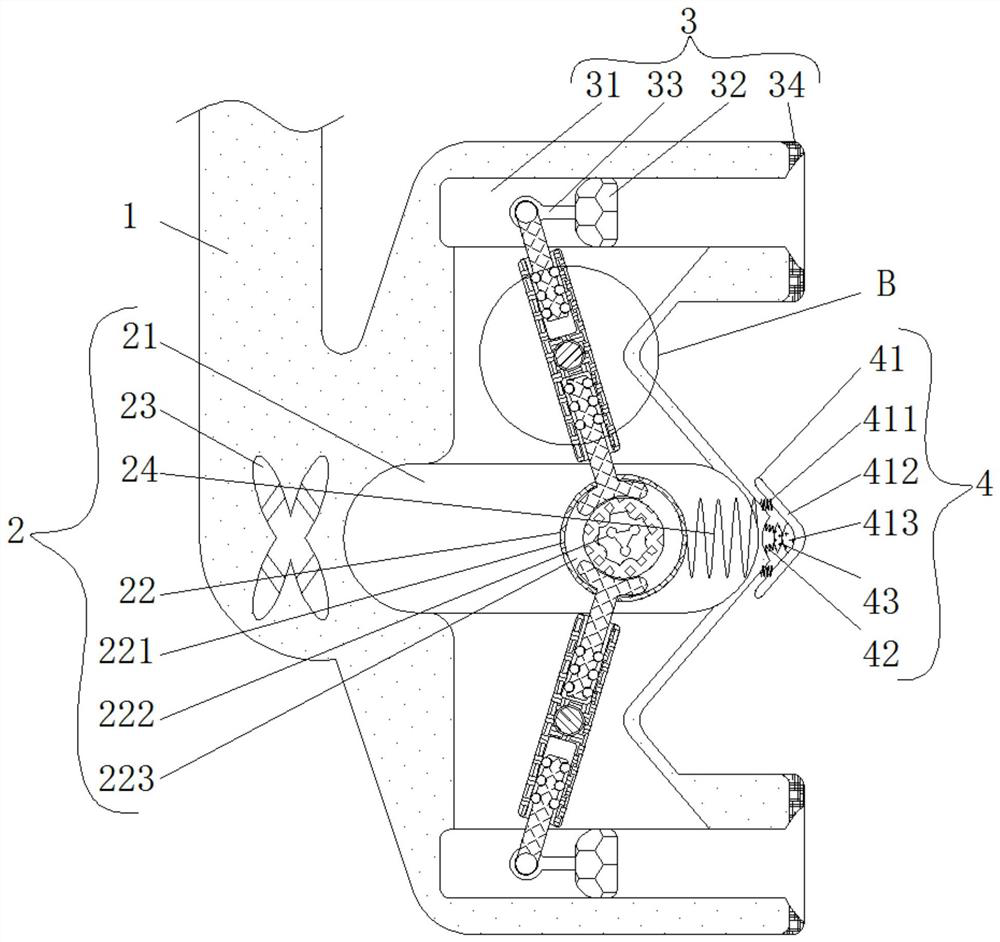
[0029] see Figure 1-4 , an optical-mechanical-electrical-integrated operating fixture device, including a clamping member 1, a transmission mechanism 2, an air pumping mechanism 3, a trigger mechanism 4, and a rotating mechanism 5. The transmission mechanism 2 is elastically connected to the inside of the clamping member 1 and is used to push The rotating mechanism 5 rotates and works, and the transmission mechanism 2 includes a movable groove 21, a stopper 22, an electromagnet 23 and a spring 24. The movable groove 21 is opened inside the clamping part 1, and the inside of the movable groove 21 is movably connected with a limiter 22. , the limiter 22 includes a moving part 221, a magnetic block 222 and an annular groove 223, the right side of the moving part 221 is fixedly connected with the spring one 24, the shape of the moving part 221 is a sphere and the material of the moving part 221 is a hard high-strength material , the moving part 221 plays the role of fixation and ...


PUM


Abstract

The invention relates to the technical field of optomechatronic equipment research and development, and discloses an optomechatronic integrated operation clamp device which comprises a clamping piece, a transmission mechanism, an air exhaust mechanism, a triggering mechanism and a rotating mechanism. The transmission mechanism is elastically connected to the interior of the clamping piece and used for pushing the rotating mechanism to rotate and work; and both the top and the bottom of the clamping piece are movably connected with the air exhaust mechanism and used for achieving the air exhaust fixing effect. According to the optomechatronic integrated operation clamp device, the rotating mechanism is driven by the transmission mechanism to operate, and then through cooperative use of the rotating mechanism and the air exhaust mechanism, when a rotating rod rotates, a telescopic rod is driven by the rotating rod, so that the effect of pulling a piston to move leftwards is achieved, the aim of exhausting air inside a rubber ring is effectively fulfilled, then the clamping piece has a certain adsorption force on an object, the situation that the object falls off in the conveying process is effectively prevented, automatic control is implemented, and operation safety of equipment is guaranteed.

Description

technical field [0001] The invention relates to the technical field of optical-mechanical-electrical equipment research and development, in particular to an optical-mechanical-electrical integrated operating fixture device. Background technique [0002] Mechatronics is also known as mechanical and electronic engineering. With the rapid development of mechatronics technology, the concept of mechatronics has been widely accepted and widely used by us. With the rapid development and wide application of computer technology, mechatronics technology has gained unprecedented Development, when using mechatronic equipment to clamp objects, the clamps used often fail to clamp, causing the objects to fall. [0003] Almost all modern automatic production equipment integrates mechatronics equipment, which can not only achieve better control, but also be more intelligent and humanized. However, when the fusion of mechatronics is used for sorting, clamping mechanisms often occur If you ca...

Claims


Application Information

Patent Timeline
Patent Type & Authority Applications(China)
IPC IPC(8): B25B11/00
CPCB25B11/005B25B11/002
Inventor 陈斌
Owner 陈斌
Why Eureka
Try Eureka