High-rigidity lead screw transmission and lathe bed system
A technology of screw drive and high rigidity, which is applied in the direction of large fixed members, metal processing machinery parts, metal processing equipment, etc., can solve the problems of easy deformation and poor rigidity of the screw rod, reduce the vibration of the screw rod, improve the rigidity and Stability and the effect of improving the bearing life
- Summary
- Abstract
- Description
- Claims
- Application Information
AI Technical Summary
Problems solved by technology
Method used
Image
Examples
Embodiment 1
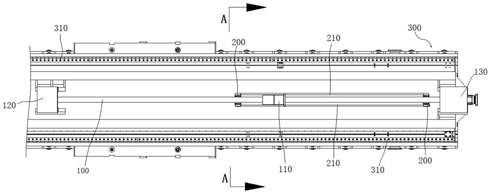
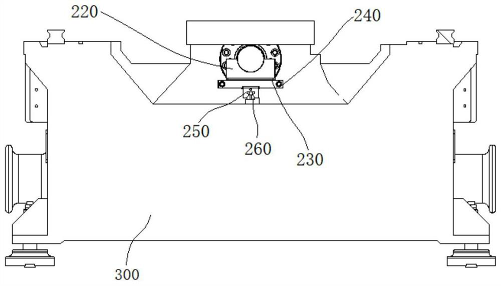
[0046] to combine Figure 1-Figure 11 , a high-rigidity screw drive and bed system in this embodiment, including a bed 300 and a screw 100 arranged on the bed 300, the two sides of the bed 300 in the length direction are respectively provided with separate motor installations Seat 330 and bearing mounting seat 340, wherein motor mounting seat 330 and bearing mounting seat 340 are used to install motor seat 120 and tail end seat 130 respectively, split structure is convenient for processing, and motor mounting seat 330 and bearing mounting seat 340 are connected There is a connecting shin plate 350. Compared with the conventional gantry milling machine, the motor seat 120 and the tail end seat 130 in this embodiment are correspondingly widened, and are connected together by the connecting shin plate 350, which can effectively improve the rigidity of the screw drive. and stability.
[0047] Such as Figure 4 As shown, in this embodiment, the two ends of the screw mandrel 100 a...
Embodiment 2
[0055] A high-rigidity screw drive and bed system in this embodiment has a basic structure as in Embodiment 1. Furthermore, in this embodiment, an anti-wear pad is provided on the top arc surface of the auxiliary support block 220 to prevent wear. The gasket is an arc gasket matched with the arc surface, and the anti-wear gasket can prevent the top of the auxiliary support block 220 from wearing out. When the anti-wear gasket wears out, it can be directly replaced with a new anti-wear gasket to ensure It can fully contact and support the screw rod 100 . The position corresponding to the arc surface and the anti-wear gasket is provided with an oil outlet, and the oil outlet is connected with the lubricating oil pipeline, and the lubricating oil is sprayed into the contact surface of the screw mandrel 100 and the anti-wear gasket, and the wire The movement of the rod 100 plays the role of lubricating and cooling, which effectively improves the service life of the screw rod 100 ....
Embodiment 3
[0060] A high-rigidity screw drive and bed system in this embodiment has a basic structure as in Embodiment 2. Furthermore, in this embodiment, a plurality of sheet metal joint surfaces are provided on the side wall of the base near the guide rail 310 in the collecting tank 360 370, the sheet metal joint surface 370 is used to connect with the metal protective shell, can wrap the guide rail 310 inside, change the sheet metal joint surface 370 at the bottom of the guide rail 310 to the inside, prevent water seepage and leakage, improve the water resistance of the machine tool, and improve the use The worker's working ground is cleaned.
[0061] In this embodiment, the bottom of the bed 300 is provided with a plurality of anchor bolts 301, and the plurality of anchor bolts 301 is more convenient for horizontal adjustment and more stable for support.
[0062] In this embodiment, the side of the bottom of the column support 320 close to the guide rail 310 is provided with an incli...
PUM
 Abstract
Description
Claims
Application Information
 - R&D
- Intellectual Property
- Life Sciences
- Materials
- Tech Scout
- Unparalleled Data Quality
- Higher Quality Content
- 60% Fewer Hallucinations
Browse by: Latest US Patents, China's latest patents, Technical Efficacy Thesaurus, Application Domain, Technology Topic, Popular Technical Reports.
© 2025 PatSnap. All rights reserved.Legal|Privacy policy|Modern Slavery Act Transparency Statement|Sitemap|About US| Contact US: help@patsnap.com


