
Method for predicting the remaining service life of a saw band, and bandsaw machine

A technology of band saw machine and saw band, which is applied in the direction of sawing machine accessories, sawing machine devices, measuring devices, etc., and can solve problems such as high cost, prone to sensor failure, and extensive maintenance

Pending Publication Date: 2021-12-21
KEURO BESITZ & EDV DIENSTLEISTUNGS
View PDF1 Cites 0 Cited by
  • Summary
  • Abstract
  • Description
  • Claims
  • Application Information

AI Technical Summary

Problems solved by technology

[0012] In addition, the sensors used to monitor the vibration characteristics of the saw band clamped in the band saw machine during operation of the band saw machine are prone to failure and require extensive maintenance under harsh environmental conditions, or must be specially customized at high cost

Method used


Image

  • Method for predicting the remaining service life of a saw band, and bandsaw machine
  • Method for predicting the remaining service life of a saw band, and bandsaw machine
  • Method for predicting the remaining service life of a saw band, and bandsaw machine

Examples


Embodiment Construction

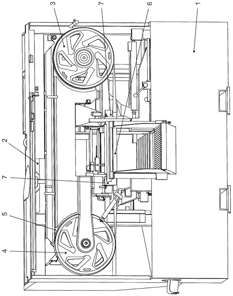
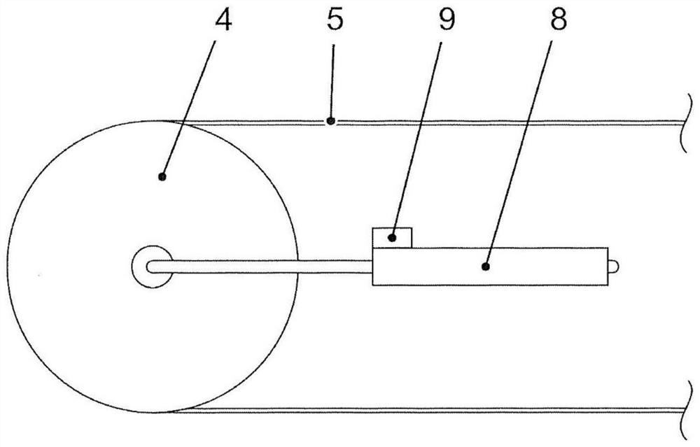
[0049] figure 1 Schematically shows a band saw machine, the band saw machine has a lower saw part 1 and an upper saw part 2, the workpiece to be sawed is placed on the lower saw part 1, and the upper saw part 2 can be positioned relative to The lower saw part 1 moves up and down. Two traveling wheels 3 , 4 are arranged in the upper saw part 2 , namely the stationary traveling wheel 3 and the horizontally movable traveling wheel 4 in this case, at least one of which is driven. The saw band 5 is tensioned around these running wheels 3 , 4 . In order to carry out the sawing movement, the saw band revolves around two running wheels 3 , 4 .

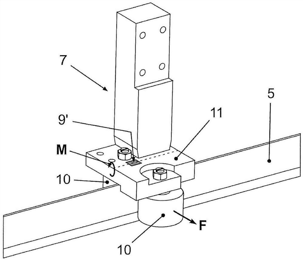
[0050] In the sawing region 6 in which the saw band 5 comes into contact with the workpiece by lowering the upper saw part 2 , the saw band 5 is swiveled by means of the two belt guides 7 from a rotation parallel to the axis of the travel wheels 3 , 4 and in the present case horizontally oriented. The movement plane is rotated into the curr...


PUM


Abstract

The invention relates to a method for predicting the remaining service life of a saw band in a bandsaw machine, wherein the behavior or properties of the saw band clamped in the sawing machine are monitored by means of at least one sensor device during operation of the sawing machine, and wherein changes in the behavior or in properties of the saw band over time established on the basis of measurement signals of the sensor device are used for making a prediction about the time at which a band will break. The behavior or properties of the saw band are indirectly monitored using the at least one sensor device by way of detecting changes to components of the sawing machine which are operatively connected to the saw band.

Description

technical field [0001] The present disclosure relates to a method according to aspect 1 for predicting the remaining service life of a saw band in a band saw machine and a band saw machine having a saw band and tensioning for the saw band device, the saw band revolves around at least two road wheels and is tensioned between them, the tensioning device acts on at least one road wheel and maintains the The tension of the saw band is basically constant. Background technique [0002] Methods of the known type make it possible to predict the remaining service life of a saw band of a band saw by monitoring the behavior of the saw band clamped in the band saw during operation of said band saw by means of at least one sensor device or Selected properties. A change over time in the behavior or selected properties of the saw band can be determined from the measurement signals of the sensor means and this change used to predict a likely or earliest point in time of band breakage. ...

Claims


Application Information

Patent Timeline
IPC IPC(8): B23D55/00B23D55/08B23Q17/20
CPCB23D55/00B23D55/08B23Q17/20B23D55/10B23D59/001B23Q17/0995B23Q2717/00G01B21/06G08B21/182
Inventor A·斯托泽S·F·克莱伯
Owner KEURO BESITZ & EDV DIENSTLEISTUNGS
Learn More